Use Remesh Faces (

)to modify the mesh on boundaries in 3D, as seen in
Figure 8-97. Supported for meshes that define their own geometric model, such as imported meshes. After remeshing the faces, use
Free Tetrahedral to fill the domains with a tetrahedral mesh.

The Remesh Faces operation also remeshes the adjacent edges which will affect the meshes on adjacent faces. If the face is adjacent to a meshed domain, also the adjacent domain mesh will be modified. Since the domain mesh will put constraints on what operations can be done on the mesh, it is typically better to first remove the domain mesh, remesh the faces, and finally mesh the domain again.
The attributes Corner Refinement,
Distribution, and
Size control the element size on boundaries and edges. Use the
Fixed Mesh attribute to keep the edge mesh on adjacent edges fixed when remeshing. Use the
Identical Mesh attribute to specify groups of boundaries or edges where identical mesh is needed.
To add a Remesh Faces node, select one or several boundaries in the
Graphics, then choose one of the following:
Specify the boundaries that you want to remesh. Use All boundaries to select all boundaries in the mesh, select
Manual to specify the boundaries by clicking in the
Graphics window or selecting from the
Selection List, or choose a named selection to refer to a previously defined selection.
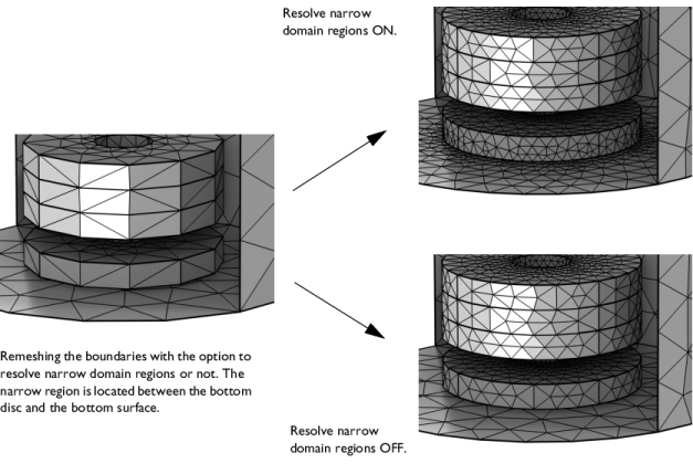
Select the check box Resolve narrow domain regions (selected by default) to allow the element size to be smaller close to narrow domain regions, as shown in
Figure 8-98. This option is useful if the adjacent domain will be filled with a tetrahedral mesh. Clear the check box to mesh each boundary without accounting for narrow domain regions. This will give a coarser mesh, as seen in the following image: