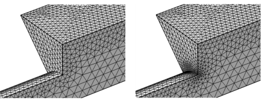
Use the Corner Refinement (

) attribute to decrease the element size at sharp corners, as shown to the right in
Figure 8-44. The node considers a vertex in 2D or an edge in 3D to be a sharp corner if the angle between the adjacent selected boundaries, with respect to the selected domain, is greater than a specified angle.
To add a Corner Refinement (

) node, select boundaries in the graphics, then choose one of the following:
To specify the boundaries, click the Active button to turn it ON and select the boundaries in the
Graphics window for which the corner refinement determines the sharp corners. When the boundary selection is
Active, the
Domain Selection section
Active button is automatically turned OFF.
Use the Minimum angle between boundaries field to specify the minimum angle between a pair of adjacent boundaries in the boundary selection for the refinement factor to apply at the vertex in 2D and edge(s) in 3D between the two boundaries. If a boundary pair is adjacent to one domain on each side (interior boundary) the corner refinement determines the angle(s) on the side(s) corresponding to the specified domain(s).
Select the Filter corners check box (default off) and the settings in the
Filter Corner Selection section to filter out a selection of the automatic selection of corners.
Use these settings to specify corners to include or exclude from the automatic selection of corners. Choose Manual in the
Selection list and click the
Active button to turn it ON to select the entities in the
Graphics window or from the Selection List, choose a named selection to refer to a previously defined selection, or choose
All edges or
All points to select all edges or points, respectively. This is useful when another handling of a selection of sharp corners is specified in
Corner Properties attributes.
Use the Element size scaling factor field to specify a refinement factor (<1) that scales the element size for the vertices in 2D and edges in 3D corresponding to the sharp corners.