Identical Mesh
Use Identical Mesh (
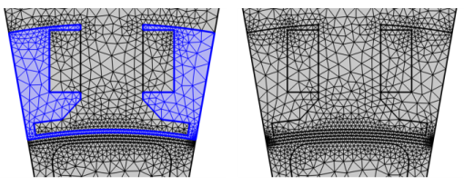
) to ensure that pairs of boundaries or edges get the same mesh, as shown in Figure 8-69.This attribute is useful when applying periodic boundary conditions and other types of symmetry conditions that require identical meshes.
Figure 8-69: One section of an impeller is meshed with the Identical Mesh attribute applied on the boundaries.The volume mesh of the section can then be copied to the other sections of the impeller.
The mesh size field is synchronized over the pairs to ensure that an identical mesh is built on the selected entities. The smallest size on each position along the faces or edges takes precedence over a larger size, as shown for the exterior boundaries of the highlighted domain in Figure 8-70.
Figure 8-70: Meshes built without (left) and with (right) Identical Mesh applied on the periodic boundaries. Right: The size field is synchronized between the entity pairs for each position.
For meshes conforming with geometry, Identical Mesh can only be added as a global attribute to ensure that the identity mapping is kept through the meshing sequence. The domains can be meshed directly after applying an Identical Mesh attribute.
In meshes that define their own geometric entities, it can only be added as a local attribute to a remeshing operation as the number of entities can change throughout the sequence. It is therefore recommended to remesh the boundaries with applied Identical Mesh as late as possible in the meshing sequence.
Use Edge Map, One-Point Map, or Two-Point Map to control how to map the entities from one group to the other.
Premeshed entities
When an entity is premeshed (and not included in the current operation), the identical operation preserves the identical mesh by effectively copying the mesh from the meshed entity to the entity to be meshed. On the other hand, if an entity is not meshed and not included in the current operation, any sizing attribute or distribution assigned to that entity is ignored. For example, take the two periodic boundaries in Figure 8-69 and assume that boundary 1 and boundary 2 are specified to have identical mesh, the Size on boundary 1 (yellow in Figure 8-71) is set to Fine, and we have the following sequences of operations:
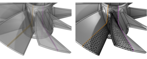
Generate mesh on boundary 1 (yellow) using a Free Triangular operation and after that mesh boundary 2 (magenta). Both boundaries get the same fine mesh.
Figure 8-71: Two boundaries where assigned to have identical mesh. The yellow boundary with a finer size setting is meshed first.
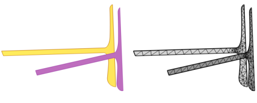
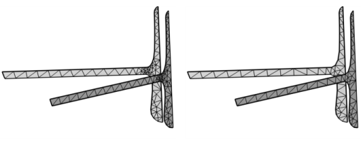
You will get the same result if you mesh boundary 1 and boundary 2 in the same Free Tetrahedral or Free Triangular operation, as seen to the left in Figure 8-72. On the other hand, if boundary 2 is meshed first and then boundary 1, then both boundary 1 and boundary 2 get the same normal sized mesh. The sizing attribute on boundary 1 will be ignored, as seen to the right in Figure 8-72.
Figure 8-72: Left: Both boundaries are meshed at the same time. Right: Meshing the magenta boundary in Figure 8-71 first. For the left case, the finer size setting is taken into account, while it is not in the right case.
To add Identical Mesh () attribute in a mesh conforming with geometry, choose one of the following:
Right-click a Mesh node and select Identical Mesh ().
Click Sizing () in The Mesh Toolbar and select Size.
To add Identical Mesh () attribute in a mesh that defines its own geometric model, choose one of the following:
Right-click a mesh operation in the Model Builder and select Identical Mesh ().
Click on the mesh operation in the Model Builder and select Identical Mesh from the More Attributes () menu in The Mesh Toolbar.
Type of Identity
This section is only visible in 3D. From the Geometric entity level list, select to apply the identity on Boundary (default) or Edge level.
First Entity Group
To start selecting the entities for the first entity group, click the Active button to toggle between turning ON and OFF selections. Select the entities in the mesh from in the Graphics window or from the Selection List window. If you activate this selection, the Graphics window shows the mesh of the source sequence such that you can select entities in this mesh.
Second Entity Group
To start selecting the entities for the first entity group, click the Active button to toggle between turning ON and OFF selections. Select the entities in the mesh from in the Graphics window or from the Selection List window. If you activate this selection, the Graphics window shows the mesh of the source sequence such that you can select entities in this mesh.
For a tutorial that uses Identical Mesh, see Permanent Magnet Motor in 3D:
Application Library path ACDC_Module/Devices,_Motors_and_Generators/pm_motor_3d.