Use Copy (

) to copy meshes within the same meshing sequence or between different meshing sequences (belonging to the same or different components). The dimension of the source meshing sequence must be less than or equal to the dimension of the destination meshing sequence. You can also copy a mesh from a mesh part to the meshing sequence in a component.

The Copy feature can be useful if you start off with an imported mesh and then want to modify it by adding a boundary layer mesh or running a solver that modifies it, such as the adaptive solver. It also makes it possible to add geometry, such as for defining a surrounding domain, to an imported mesh while still keeping the imported mesh on the “original geometry”. Use the following steps to copy an imported mesh into another component’s geometry:
From the Mesh list, select the meshing sequence or mesh part to copy from (or
None, which is the default in 1D); then (for meshing sequences only) click
Copy to copy the updated source mesh. By default, the meshing sequence in which the
Copy node resides is selected. When this sequence is selected, the
Copy button is unavailable. If you have parameterized the geometry or mesh and plan to run a parametric sweep, select the
Build source mesh automatically check box to ensure that the source mesh and geometry are updated before copying. Otherwise, you have to manually rebuild the source mesh and click the
Copy button if you want to use an updated source mesh. Click the
Go to Source button (

) to move to the main
Mesh node of the source mesh.
Select the geometric entity level of the copy from the Geometric entity level list. The possible choices are
Entire geometry,
Domain (the default),
Boundary, or
Edge (3D only). For
Entire geometry, the sections below are not available.
Use this section to select the entities to copy mesh from in the specified source mesh. From the Selection list, choose
All domains (for example) or choose
Manual to pick the entities from the
Graphics window. Click the
Active button to toggle between turning ON

and OFF

selections. Select the entities to copy the mesh from in the
Graphics window. If you activate this selection, the
Graphics window shows the mesh of the source sequence such that you can select entities in this mesh.
Click the Swap Source and Destination button (

) to swap the entities in the source list above and the entities in the destination list in the
Destination Entities section below.
This section is similar to the Source Entities section above, but you use it to define the geometric entities in the destination to which you want to copy the mesh.
Select Automatic (the default) to let the software determine the proper copy method, select
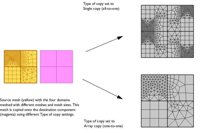
Single copy (all-to-one) to let the entire source mesh be copied onto each destination entity separately, and select
Array copy (one-to-one) to let each single source entity mesh be copied onto one entity per destination component.

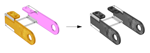
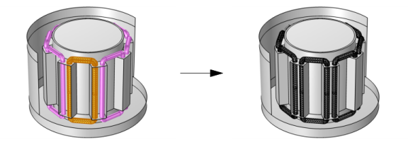
The Array copy (one-to-one) setting also supports copy from one or several connected components of meshed domains, to several other similar components, as shown in
Figure 8-41.

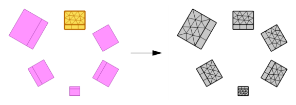
Use the Automatic setting to let the software choose between
Single copy (all-to-one),
Array copy (one-to-one), or a mixture of the two.
Figure 8-42 shows a mix of
Single copy (all-to-one) and
Array copy (one-to-one).

Select the Smooth across removed control entities check box to smooth the transition in element size across removed control entities. You can specify the number of smoothing iterations in the
Number of iterations field. In the
Maximum element depth to process field you can specify the maximum element depth, from the removed control entity.


