Edge Map
Use the Edge Map () attribute to specify the orientation of the source mesh on the destination for a Copy, Copy Face, or a Copy Domain node. Using this node, the source mesh of the copy operation is transformed so that the source edge of the Edge Map node is mapped onto the destination edge with the specified orientation, as shown in Figure 8-54.
Figure 8-54: The left image shows the resulting mesh after copying the triangle mesh on the right circle to the left. The right image shows the resulting mesh with an Edge Map applied, generating a mirrored mesh on the circles. The yellow edge species the edge on the source that is mapped onto the magenta edge on the destination.
To add an Edge Map () node, choose one of the following:
Right-click the Copy, Copy Face or a Copy Domain operation and select Edge Map ()
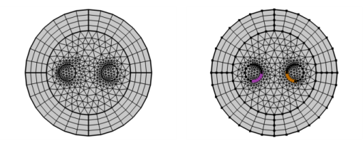
Select the Copy, Copy Face, or a Copy Domain node in the Model Builder, click More Attributes () on The Mesh Toolbar and select Edge Map.
Then enter the properties using the following sections:
Edges
Click the Active button to toggle between turning ON and OFF selections.
Activate the Source edge list and select the edge that you want to define as the source edge in the Graphics window.
Activate the Destination edge list and select the edge that you want to define as the destination edge in the Graphics window.
Orientation
Select Automatic orientation to let the software determine the orientation of the mesh of the source edge on the destination edge (this is the default), select Same orientation to let the mesh of the source edge be copied to the destination edge according to the directions of the edges, or select Opposite orientation to let the mesh of the source edge be copied to the destination edge in the opposite direction.