Use Remesh Edges (

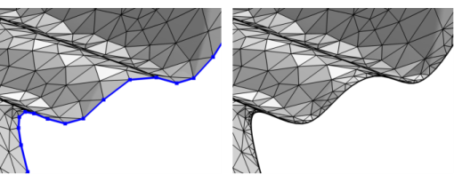
) to modify the edge mesh (3D) or boundary mesh (2D) of a mesh that defines its own geometric model, such as an imported mesh, as seen in
Figure 8-96.
The attributes Corner Refinement,
Distribution, and
Size control the element size on edges. Use the
Identical Mesh attribute to specify boundaries or edges where identical mesh is needed.
To add a Remesh Edges node, select one or several edges (3D) or boundaries (2D) in the
Graphics, then choose one of the following:
Specify the edges (3D) or boundaries (2D) that you want to remesh. Use All edges/All boundaries to select all entities of that dimension in the mesh, select
Manual to specify the edges/boundaries by clicking in the
Graphics window or selecting from the
Selection List, or choose a named selection to refer to a previously defined selection.
Select the Preserve shape of adjacent faces check box (selected by default) to allow the operation to analyze the shape of adjacent faces to preserve the shape of the faces when remeshing the edges. Clear the check box to use a linear representation and only account for the shape of the edge when remeshing it.