|
|
|
|
Note that creating faces can modify the number of geometric boundaries in the mesh. Thus when you are adding this operation to a meshing sequence that is conforming with the component’s geometry, a new meshing sequence that is defining its own geometric model is automatically created, and the Create Faces node is added to this new sequence. For more information, see The Mesh Node.
|
|
|
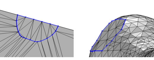
The created faces are formed using a simple surface mesh. You can add a Free Triangular to remesh the generated face. See also Remeshing Imported Meshes.
|
|
•
|
Right-click in the Graphics window to open The Graphics Context Menu and select Create Faces (
|
|
•
|
For a 3D mesh, it is available from the Create Entities menu (
|
|
•
|
|
|
Most physics require a mesh on the domains. Use the Free Tetrahedral, Swept, and Boundary Layers operations to fill the domains with domain elements.
|
|
|
See STL Import 1 — Generating a Geometry from an Imported Mesh: Application Library path COMSOL_Multiphysics/Meshing_Tutorials/stl_vertebra_import.
|
|
|