Fill Holes
Use Fill Holes () to repair an imported 3D surface mesh that might have minor holes, as seen in Figure 8-55.
Figure 8-55: Repairing small holes, bounded by the blue edges, in a surface mesh using the Fill Holes operation (left). The right image shows the repaired mesh.
To add a Fill Holes () node, select one or more boundaries in which to fill holes, then choose one of the following:
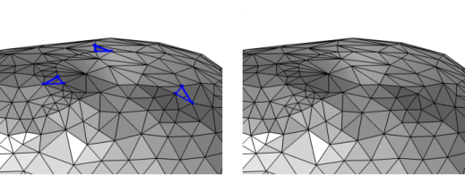
Right-click in the Graphics window and in the The Graphics Context Menu, select Fill Holes () from the Cleanup and Repair menu.
In the Mesh toolbar, click Cleanup and Repair () and choose Fill Holes.
Right-click the Mesh node and choose Fill Holes () from the Cleanup and Repair menu.
Enter the properties for the Fill Holes node using the following sections:
Boundary Selection
The operation to fill a hole requires a face (boundaries) selection and finds holes in and between all selected faces. Only faces isolated in void or unmeshed domains can be selected.
Fill Holes
Holes that have a perimeter less than the tolerance are filled. You specify the tolerance using the Maximum hole perimeter list:
Select Automatic (the default) to use a tolerance that is 10 times the mean element size of the imported mesh.
Select Manual to specify the tolerance (SI unit: m) in the Perimeter field.
The Join with selected boundaries check box is selected by default. If selected, the created mesh elements (triangles) that fill the hole are added to the surrounding face. If you clear this check box, or if the hole is adjacent to more than one face, the created mesh elements form a new face.
Select the Create domains check box (selected by default) to automatically form domains for each (connected) finite void region that is defined by the imported surface mesh and analyze these domains with respect to the mesh that might already exist in the sequence. Clear the check box to not form domains, for example if more repairing is needed before the mesh forms watertight regions. Consider to later add a Create Domains operation if you clear the check box.
Most physics require a mesh on the domains. Use the Free Tetrahedral, Swept, and Boundary Layers operations to fill the domains with domain elements.
Selections of Resulting Entities
Select the Resulting domains check box to create a predefined selection in subsequent nodes in the mesh sequence. To also make the selection available in all applicable selection lists outside the mesh sequence or mesh part (in physics and materials settings, for example), select the Show in physics (Show outside part if in a mesh part) check box. These selections do not appear as separate selection nodes in the model tree. From the Color list, choose a color for highlighting the resulting objects selection. See Selection Colors and Creating Named Selections in the Mesh Sequence.
See STL Import 2 — Remeshing an Imported Mesh: Application Library path COMSOL_Multiphysics/Meshing_Tutorials/stl_vertebra_mesh_import.