Use Boundary Layers (

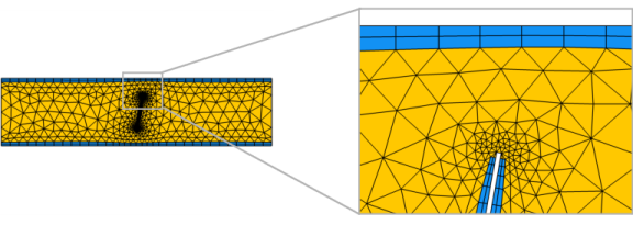
) to create a boundary layer mesh with dense element distribution in the normal direction along selected boundaries, as shown in
Figure 8-29. This type of mesh is typically used for fluid flow problems to resolve the thin boundary layers along the no-slip boundaries.
When a Boundary Layers node is added, a
Boundary Layer Properties node is automatically added as a subnode. Use this subnode to specify the boundary layers and the properties of the boundary layers. If you want to specify different boundary layer properties for more than one boundary selection, right-click the
Boundary Layers node and add additional
Boundary Layer Properties subnodes.
To add a Boundary Layers node, select boundaries (2D and 3D) or edges (for a boundary layer mesh on boundaries in 3D) in the graphics, then choose one of the following:
In the Maximum layer decrement field you can specify the maximum difference in number of boundary layers between neighboring points on boundary layer boundaries.
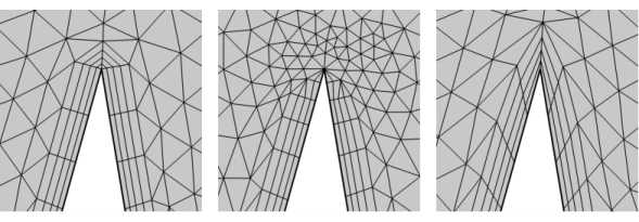
In the section Trimming in narrow corners, specify the
Trim for angles less than. This setting controls the maximum angle between adjacent boundaries for trimming to occur, as shown in
Figure 8-31. For angles between a boundary layer boundary and any other boundary, half the
Trim for angles less than is used.
Select the Smooth transition to interior mesh check box to smooth the transition in element size from the boundary layer mesh to the interior mesh. You can specify the number of smoothing iterations in the
Number of iterations field. In the
Maximum element depth to process field you can specify the maximum element depth, from the boundary layer interface, for the mesh points to be smoothed.
Specify the boundary layer method to use. From the Method list, select
Latest version (default) to use the most recent version of the boundary layer mesher, or select
Legacy version 6.1 or
Legacy version 6.0 to use similar methods as used in version 6.1 and version 6.0, respectively. For
Legacy version 6.0, the directions in the boundary layers are kept straight in all layers, otherwise they may bend to improve the quality. The
Legacy version 6.1 option affects the deformation of the mesh to make room for the boundary layers; more recent versions of COMSOL Multiphysics provide a more sophisticated method that allows you to create thicker boundary layers with higher element quality.