Boundary Layer Properties
Use the Boundary Layer Properties () attribute to specify the location of the boundary layers and the properties, such as the number of layers and thickness of the boundary layers, as shown in Figure 8-32.
Figure 8-32: Boundary layers added to selected boundaries (highlighted in blue). Two element layers have been generated in the left mesh and five layers in the mesh on the right-hand side.
By default, one Boundary Layer Properties node is added as a subnode to a Boundary Layers node. To add additional nodes choose one of the following:
Select the Boundary Layers node, select boundaries or edges in the Graphics window, and then choose Boundary Layer Properties from the More Attributes menu () on The Mesh Toolbar.
Right-click the Boundary Layers node and choose Boundary Layer Properties ().
Then enter the properties using the following sections:
Geometric Entity Selection
Define the edges (for faces in 3D) or boundaries where to add boundary layers. Choose Manual in the Selection list to select the entities in the Graphics window, choose a named selection to refer to a previously defined selection, or choose All boundaries or All edges to select all boundaries or edges respectively.
Setting Geometric entity level: Domain or Boundary in the Boundary Layers node changes the name of this section to Boundary Selection or Edge Selection, respectively.
Layers
The default Number of layers is 8.
The default Stretching factor is 1.2. This field is used to specify the increase in thickness between two consecutive boundary layers as a scaling factor; for example, entering 1.3 means that the thickness increases by 30% from one layer to the next.
To specify the thickness of the boundary layer mesh, choose an option from the Thickness specification list: Automatic (the default), First layer, or All layers.
If Automatic is kept, for each boundary element, the local thickness of the first layer is computed as 5% of the height of the adjacent element (in the direction orthogonal to the boundary element). Enter the Thickness adjustment factor (default is 1) to specify a scaling of the thickness of the first layer.
If First layer is selected, specify the Thickness of the first element layer — the layer adjacent to the corresponding boundary.
If All layers is selected, specify the Total thickness of the boundary layer mesh.
The default thickness of the first layer and the total thickness of the boundary layer mesh are both determined from the specified element size in the sequence.
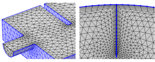
Boundary Layer Meshing — Exploring the Settings:
Application Library path COMSOL_Multiphysics/Meshing_Tutorials/valve_boundary_layers.