
|
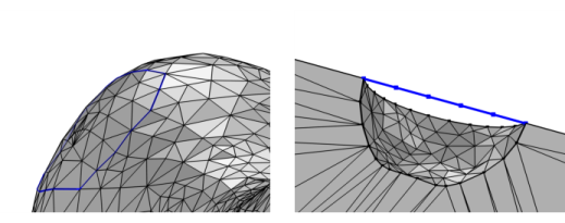
Note that creating edges can modify the number of geometric edges in the mesh. Thus, when you are adding this operation to a meshing sequence that is conforming with the component’s geometry, a new meshing sequence that is defining its own geometric model is automatically created, and the Create Edges node is added to this new sequence. For more information, see The Mesh Node.
|
|
•
|
For a 3D mesh, it is available from the Create Entities menu (
|
|
•
|
|
It is only possible to select mesh edges on boundaries in 3D which are visible in the Graphics window. Use Click and Hide and the clipping tools to get access to interior boundaries. Rotate the mesh to make the opposite side come into view.
|
|
•
|
Select Element size (the default) to specify the maximum element size (SI unit: m), which you enter in the Maximum element size field. The value is a relative number (default: 0.1 in 3D and 1/15 in 2D). This value is multiplied with the size of the bounding box.
|
|
•
|
Select Fixed number of elements to use a fixed number of mesh elements, which you enter into the Number of elements field (default: 1).
|
|
•
|
Select Explicit distribution to use an explicit, user-defined element distribution. To define the distribution of mesh elements, enter a vector-valued expression defining a strictly increasing sequence of nonnegative numbers (using comma-separated numbers) in the Relative placement of vertices along edge field, specifying the relative arc length values of the mesh vertices along the edge or boundary. Select the Reverse direction check box to reverse the direction of the explicit distribution.
|
|
•
|
Select Predefined distribution to specify properties of a predefined distribution method where the element size can be exponentially or linearly increasing or decreasing. From the Growth rate list, select Exponential to let the distribution method be a geometric sequence and Linear for an arithmetic sequence. In addition, specify values in the Number of elements and Element ratio fields to determine the number and ratio of elements in the distribution. Select the Symmetric distribution check box to make the predefined size distribution symmetric. Select the Reverse direction check box to reverse the direction of the predefined distribution.
|
|
See STL Import 1 — Generating a Geometry from an Imported Mesh: Application Library path COMSOL_Multiphysics/Meshing_Tutorials/stl_vertebra_import.
|