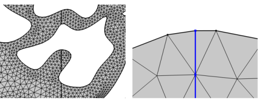
Use Intersect with Line (

) to intersect the elements of an imported mesh with a straight line, as shown in
Figure 8-75. The selected geometric entities are partitioned by the line. A selection of domains will also lead to a partitioning of adjacent boundaries.
To add a Intersect with Line (

) node, select domains in the
Graphics, and then choose one of the following:
Enter the properties for Intersect with Line using the following sections:
Define the geometric entities to intersect. From the Geometric entity level list: Choose
Entire geometry,
Domain, or
Boundary to specify the domains or boundaries to partition with the line or choose a named selection to refer to a previously defined selection. The option
Entire geometry selects all domains and boundaries.
From the Specify list, choose
Coordinates (the default) to specify the positions of a point on the line. Enter values in the corresponding
x and
y fields. Alternatively, select
Vertex to select a vertex.
From the Specify list, choose
Direction vector (the default) to specify the direction of the line using a vector. Enter values in the corresponding
x and
y fields. Alternatively, select
Second point coordinates or
Second vertex to let the line and its direction be defined by two points. For
Second point coordinates, specify the coordinates in the corresponding
x and
y fields. For
Second vertex, select a vertex.
Click the Active button to toggle between turning ON and OFF the vertex selection. To add a vertex to the selection, click on a vertex in the
Graphics window or add one using the
Selection List.
Use the Repair tolerance list to control the snapping distance by choosing
Automatic (the default),
Relative, or
Absolute. Choose
Relative to enter a value in the
Relative tolerance field. This value is relative to the length of the longest side of the mesh bounding box. Select
Absolute to specify a value in the
Absolute tolerance field. When the operation is built with either of the settings
Automatic or
Relative, the values in the
Relative tolerance (for
Automatic only) and
Absolute tolerance fields are automatically updated to be an average of the distances the mesh vertices were actually moved.
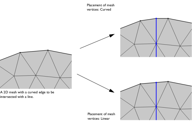
Use the Placement of mesh vertices setting to specify if the new mesh vertices on the intersecting edges will be placed using a
Curved (default) or
Linear representation. See
Figure 8-76.
Select the Intersection edges,
Entities above, and/or
Entities below check boxes to create predefined selections in subsequent nodes in the mesh sequence. To also make the selections available in all applicable selection lists outside the mesh sequence or mesh part (in physics and materials settings, for example), select the
Show in physics (
Show outside part if in a mesh part) check box or choose an option from the
Show in physics (
Show outside part if in a mesh part) list:
All levels,
Domain selection,
Boundary selection, or
Point selection. To keep the selection local to the mesh sequence/part, choose
Off. The default is
Domain selection, which is suitable for use with materials and physics defined in domains. For use with a boundary condition, for example, choose
Boundary selection. These selections do not appear as separate selection nodes in the model tree. From the
Color list, choose a color for highlighting the resulting objects selection. See
Selection Colors and
Creating Named Selections in the Mesh Sequence.