You are viewing the documentation for an older COMSOL version. The latest version is
available here.
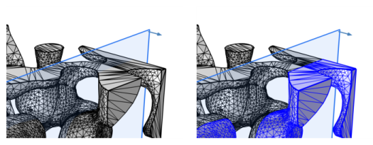
Use Intersect with Plane (

) to intersect the elements of an imported mesh with one or several parallel planes. The selected geometric entities are partitioned by the planes, as seen in
Figure 8-77. A selection of domains will also lead to a partitioning of adjacent boundaries and edges. Closed regions formed by the edges in the intersection plane will be filled with meshed faces by default (see
Intersections for more information).
To add an Intersect with Plane (

) node, select the entities to intersect in the
Graphics window, then choose one of the following:
|
•
|
Right-click the Mesh node and select Intersect with Plane (  ) from the Booleans and Partitions menu.
|
Enter the properties for the Intersect with Plane node using the following sections:
Define the geometric entities to intersect. From the Geometric entity level list: Choose
Entire geometry,
Domain,
Boundary, or
Edge to specify the domains, boundaries, or edges to partition with the plane or choose a named selection to refer to a previously defined selection. Only unmeshed domains are supported. The option
Entire geometry selects all boundaries and edges.
The layout of the Plane Definition section depends on the selection in the
Plane type list, where you select how to define the plane. Choose one of the following types:
In the Plane list, select one of the global coordinate planes
xy,
yz,
zx,
yx,
zy, or
xz, denoting the first and second axes of the plane’s local coordinate system. Specify an offset using one of the following settings in the
Offset type list:
|
•
|
Distance (the default) to define the distance from the coordinate plane in the third axis’ direction using the z-coordinate, x-coordinate, or y-coordinate field (default value: 0; that is, no offset).
|
|
•
|
Through vertex to define the position of the plane by selecting a vertex. The plane’s position then contains that vertex. Click the Active button to toggle between turning ON and OFF the Offset Vertex selections.
|
Select a planar face in the Graphics window that is parallel to the plane you want to create. The list below shows the selected face. Click the
Active button to toggle between turning ON and OFF the
Planar Face selections. Specify an offset using one of the following settings in the
Offset type list:
|
•
|
Distance (the default) to define the distance in the Offset in normal direction field. Default value: 0; that is, no offset. Enter a value to offset the plane along the normal of the planar face. The normal direction is indicated in the Graphics window, showing arrows in the corners of the visualization of the plane.
|
|
•
|
Through vertex to define the position of the plane by selecting a vertex. The plane’s position then includes the position of that vertex. Click the Active button to toggle between turning ON and OFF the Offset Vertex selections.
|
Select a planar edge (that is not straight) in the Graphics window that is parallel to the plane you want to create. The list below then shows the selected edge. Click the
Active button to toggle between turning ON and OFF the
Planar Curved Edge selections.
|
•
|
Distance (the default) to define the distance in the Offset in normal direction field. Default value: 0; that is, no offset. Enter a value to offset the plane along the normal of the plane containing the edge. The normal direction is indicated in the Graphics window, showing arrows in the corners of the visualization of the plane.
|
|
•
|
Through vertex to define the position of the plane in the third direction by selecting a vertex. The plane’s position then includes the position of that vertex. Click the Active button to toggle between turning ON and OFF the Offset Vertex selections.
|
Under Normal vector, in the
x,
y, and
z fields (SI unit: m), enter the components of the normal vector.
Under Point on plane, from the
Specify list, choose
Coordinates (the default) or
Vertex. For
Coordinates, enter the coordinates for a point on the plane in the
x,
y, and
z fields (SI unit: m). For
Vertex, select a vertex in the geometry, or if available, use a user-defined vertex selection.
In each of the lists First vertex,
Second vertex, and
Third vertex, select a vertex by first clicking the corresponding
Active button and then selecting a vertex in the
Graphics window. This creates a plane parallel to a plane through the three vertices.
Specify an offset in the Offset in normal direction field (default value: 0; that is, no offset). The normal direction is indicated in the
Graphics window, showing arrows in the corners of the visualization of the plane. Reverse the orientation of the plane by selecting the
Reverse normal direction check box.
Select the Additional parallel planes check box to add several planes which will be parallel to the one specified above. Enter the desired plane offsets in the
Distances field (using comma- or space-separated numbers), specifying the distances between each additional plane and the original plane. Both positive and negative values are allowed. Alternatively, use the
Range button (

) to create an array of values. The orientation of the first plane determines the orientation of generated faces and on what side additional planes are placed. Reverse the offset direction by selecting the
Reverse direction check box (the positive direction is the normal direction of the first plane).
Use the Create intersection faces option to fill closed regions formed by the edges in the intersection plane (default ON). This results in planar faces meshed with an unstructured triangular mesh. For a domain selection, faces will only be created inside the selected domains. A warning that no faces could be created might be expected if only one boundary has been selected. To get rid of the warning, clear the
Create intersection faces check box.
Use the Repair tolerance list to control the snapping distance by choosing
Automatic (the default),
Relative, or
Absolute. Choose
Relative to enter a value in the
Relative tolerance field. This value is relative to the length of the longest side of the mesh bounding box. Select
Absolute to specify a value in the
Absolute tolerance field. When the operation is built with either of the settings
Automatic or
Relative, the values in the
Relative tolerance (for
Automatic only) and
Absolute tolerance fields are automatically updated to be an average of the distances the mesh vertices were actually moved.
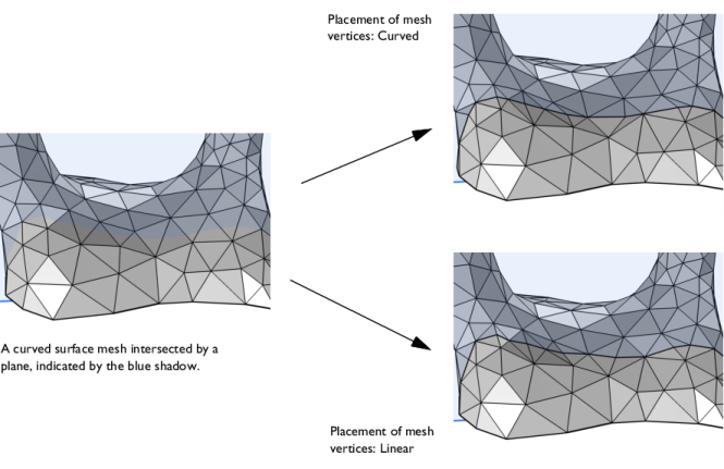
Use the Placement of mesh vertices setting to specify if the new mesh vertices on the intersection edge will be placed using a
Curved (default) or
Linear representation. See
Figure 8-76.
Select the Cleanup resulting mesh check box to allow short mesh edges to be removed. Mesh edges shorter than the specified
Repair tolerance will be collapsed as long as this does not result in an invalid mesh.
Select the Intersection Faces,
Intersection edges,
Entities above, and/or
Entities below check boxes to create predefined selections in subsequent nodes in the mesh sequence. To also make the selections available in all applicable selection lists outside the mesh sequence or mesh part (in physics and materials settings, for example), select the
Show in physics (
Show outside part if in a mesh part) check box or choose an option from the
Show in physics (
Show outside part if in a mesh part) list:
All levels,
Domain selection,
Boundary selection,
Edge Selection or
Point selection. To keep the selection local to the mesh sequence/part, choose
Off. The default is
Domain selection, which is suitable for use with materials and physics defined in domains. For use with a boundary condition, for example, choose
Boundary selection. These selections do not appear as separate selection nodes in the model tree. From the
Color list, choose a color for highlighting the resulting objects selection. See
Selection Colors and
Creating Named Selections in the Mesh Sequence.