Use Imprint (

) to partition faces in a mesh by imprinting faces, edges, or vertices onto them, as seen in
Figure 8-73. The mesh elements are partitioned by imprinted edges and vertices.

To add an Imprint node, select entities to imprint in the
Graphics, and then choose one of the following:
Enter the properties for Imprint using the following sections:
Select the geometric entity level of the source from the Geometric entity level list. The possible choices are
Boundary,
Edge (the default), or
Point.
To start selecting the entities to imprint, from the Selection list, choose
All edges (for example) or choose
Manual to pick the entities from the
Graphics window. Click the
Active button to toggle between turning ON

and OFF

selections. Select the entities to imprint in the mesh from in the
Graphics window. If you activate this selection, the
Graphics window shows the mesh of the source sequence such that you can select entities in this mesh.
Select the Group adjacent edges check box to automatically extend an edge selection to neighboring edges that seem to be part of the loop. If you clear this check box, each edge can be selected or deselected manually. This option is only available when
Geometric entity level is set to
Edge.
This section is similar to the Source Entities section above, but you use it to define the boundaries on which you want to imprint the source entities.
Select Destination (default) from the
Imprint on list to imprint the source faces on the destination faces. Select
Destination and Source to also imprint the destination faces on the source faces. This option is only available when
Geometric entity level is set to
Boundary in the
Source section.
Use the Maximum distance setting to control the maximum distance to bridge when imprinting entities of a mesh. Choose
Relative to enter a value in the
Relative distance field. This value is relative to the length of the longest side of the mesh’s bounding box. Select
Absolute to specify a value in the
Absolute distance field. When the operation is built with the setting
Automatic (the default), the value in the
Absolute distance field is automatically updated to correspond to the actually used distance. The automatic tolerance is based on the size of the bounding box of the mesh.
Use the Placement of mesh vertices setting to specify if the mesh vertices of the entities to be removed will be placed on the
Curved (default) or
Linear representation of the destination faces.
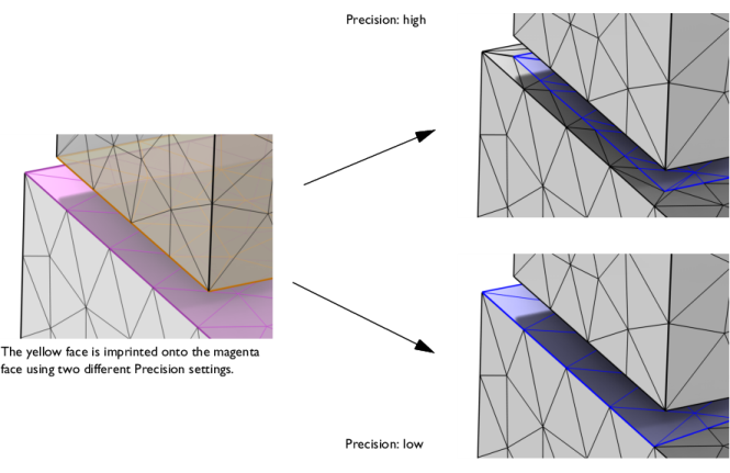
Use the Precision field or slider to specify the accuracy of the imprint, as shown in
Figure 8-74. A low precision will give a sloppier matching, meaning that regions of entities with approximately the same shape will be matched without imprinting, while high precision gives a more accurate imprint but also means that small entities and details can appear.