Use Create Vertices (

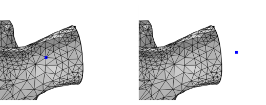
) to create vertices in a mesh. Convert existing mesh vertices into vertex elements or create new vertex elements, as shown in
Figure 8-47. The new vertices can be created in empty space or be created to overlap existing mesh.
To add a Create Vertices node, choose one of the following:
Enter the properties for the Create Vertices node using the following sections:
For the Specify option, select
Mesh vertices (the default) to specify positions by clicking on mesh vertices in the Graphics window. Alternatively, choose
Coordinates to specify the positions of the vertices.
Click the Active button to toggle between turning ON and OFF the mesh vertex selection. This enables selection by clicking in the Graphics window. When the
Active button is toggled ON, the
Mesh Rendering will automatically be turned ON to facilitate the selection of vertices. It is possible enter the exact
x-,
y-, and (3D only)
z-coordinates manually in the table, but the
Coordinates vertex specification is better suited for this purpose. Selected vertices are highlighted in the Graphics. Click a second time on the same vertex to remove it from the selection. Use the buttons beside the table to remove rows, clear the table, load and save table data, and to zoom in on coordinates in the table. For txt files, use either the
Spreadsheet Data Format or the
Sectionwise Data Format. Make sure that the number of columns or entries per row correspond to the dimension of the mesh and that only coordinate data is included in the file.
For the Input format setting, select
Componentwise (the default) to enter arrays of the x, y, and z components. Valid inputs for the
x,
y, and
z (3D only) fields are either arrays of the same length or scalars. If both arrays (of size bigger than one) and scalars are given, the scalars are interpreted as an array of constant value. Use the
Range button (

) if desired to create an array of coordinate values.
Alternatively, choose Pointwise to specify a table of coordinates. In each row in the table, enter comma-separated values for x, y, and z (3D only).
Use the Relative snapping tolerance field to specify a maximum distance within which the specified point will snap to the closest mesh element. If the point is not snapped to a mesh vertex, the element will be partitioned to conform with the added mesh vertex. In other words, if you add a point inside an element, it will be refined to include that point. If you create a vertex inside an unmeshed domain, the vertex will become adjacent to that domain. A vertex element will be created at the snapped point. If there are no such mesh points within the tolerance, both a mesh point and a vertex element will be created at the specified coordinates. The value in the
Relative snapping tolerance field is relative to the size of the mesh including the added vertices. It is relative to the diameter of the bounding box and must therefore be given as a value between 0 and 1. The specified points are not allowed to be within the relative snapping tolerance of each other.
Select the Resulting vertices check box to create a predefined selection in subsequent nodes in the mesh sequence. To also make the selection available in all applicable selection lists outside the mesh sequence or mesh part (in physics and materials settings, for example), select the
Show in physics (
Show outside part if in a mesh part) check box. These selections do not appear as separate selection nodes in the model tree.