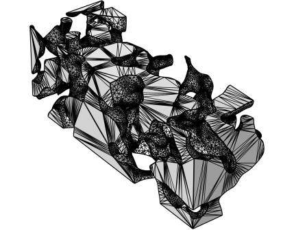
Use an Import node (

) to import a mesh from a
3MF,
PLY,
STL, or
VRML file. When you import a mesh, you can position, rotate, and scale the mesh by using one or several
Transform attributes.

To import additional meshes, add another Import node. Then COMSOL Multiphysics adds the elements of the newly imported mesh to the existing mesh.
Specify the filename in the Filename field or click the
Browse button. You can also click the downward arrow beside the
Browse button and choose
Browse From (

) to open the fullscreen
Select File window. Click the downward arrow for the
Location menu (

) to choose
Show in Auxiliary Data (

) to move to the row for this file in the
Auxiliary Data window,
Copy Location (

), and (if you have copied a file location)
Paste Location (

).
Select the Create domains check box (selected by default) to automatically form domains for each (connected) finite void region that is defined by the imported surface mesh and analyze these domains with respect to the mesh that might already exist in the sequence.
These settings are available when the Source list is set to
STL file for import of stereolithography files in 3D. Such files contain data for an unstructured triangulated surface.
The Create selections check box is selected by default to create a boundary selection of every
solid section in the file during import. Typically, there is only one such section. In that case, a selection of the entire boundary is created. This happens also when the STL file is binary and can by definition have no
solid sections. The created selections appear in a table in the
Boundary Selections section that appears below the
Import section. The table has two columns. In the right column, the name of the
solid section that the selection has been created from appears. If the section is named or if the file is binary, the name is empty. If the
Create Domain check box is selected and domains was successfully created, a table with selections for the domains appear under the
Domains Selections section. The domain selection typically get the same name as the boundary selection for the boundaries that enclose the domain. The selections appear in the same order as the corresponding sections in the file. In the left column, the name of the selection appears. By this name, which can be changed, as well as dimension of the selection, you can find the selection in the model.
These settings are available when the Source list is set to
3MF file,
PLY file, or
VRML file for import of files of the 3MF, PLY, or VRML formats. Such files contain data for a surface mesh containing triangle or quadrilateral (PLY only) elements.
Select the Merging coinciding mesh vertices check box to merge mesh vertices that coincide within the merge tolerance during import. Specify the
Tolerance by selecting one of these options:
The sections Domain Selections,
Boundary Selections,
Edge Selections, and
Point Selections appear after building the
Import operation. The selections are generated during the import based on selections defined in the source. In the
Name column, the name of each selection appears. For STL file import, the source of each selection appears in
Solid section in file column (that is, which information in the imported file that was used to generate the selection). Select the name in the
Name column to highlight the selection in the
Graphics window. You can change the name of a selection by editing the corresponding table entry in the
Name column. Note that not all of these selection sections are available for all space dimensions.

