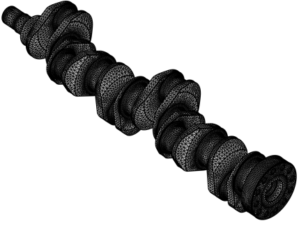
Use an Import node (

) to import 3D meshes (and planar 2D meshes) in the NASTRAN bulk data format, the most common format for exchanging 3D meshes among programs.

To import additional meshes, add another Import node. Then COMSOL Multiphysics adds the elements of the newly imported mesh to the existing mesh.
The Import operation will change the number of entities in the mesh, so unless the meshing sequence is defining its own geometric model, a new meshing sequence of this type will be set up automatically. Then, the
Import node will be added in the new sequence.
Specify the filename in the Filename field or click the
Browse button. You can also click the downward arrow beside the
Browse button and choose
Browse From (

) to open the fullscreen
Select File window. Click the downward arrow for the
Location menu (

) to choose
Show in Auxiliary Data (

) to move to the row for this file in the
Auxiliary Data window,
Copy Location (

), and (if you have copied a file location)
Paste Location (

).
If you have changed some property, the software automatically reimports the mesh when you click a build button. For import of a meshing sequence, select Build source mesh automatically (selected by default) to automatically build the source sequence and reimport the current version of the mesh. This is required when running a parametric sweep over some parameter that affects the source mesh.
To import mesh and material data from a NASTRAN file, select Mesh and materials in the
Data to import list. In this case, COMSOL Multiphysics creates
Material nodes corresponding to the data in any MAT1 and MAT10 entries in the file. Furthermore, the thickness data of any PSHELL entry in the file is stored in a
Variables node as long as it is greater than zero. To simplify the use of this data in physics interfaces, such as the
Shell interface, an
Explicit selection that contains all boundary faces associated with PSHELL entries, also becomes available. If the material data is not required, select
Only mesh to import the mesh only.
To use material data in the file to determine the partitioning of the elements, select the Partition according to material data check box (selected by default). The
Create selections check box is selected by default to automatically generate selections deduced from the file. Domain, boundary, and edge selections are created for each property id (PID) of the elements in the file. Mesh elements associated with RBE entries (RBE2 and RBE3) can form selections of all geometric entity levels. The created selections appear in
Domain Selections,
Boundary Selections,
Edge Selections, and
Point Selections sections, depending on their entity levels. The origin of each created selection is described in the
Source in file column. These selections become available for specifying geometric entities throughout the component — for instance, in Material nodes and physics interfaces. The
Allow partitioning of shells check box is selected by default to allow the boundary partitioning algorithm to split the boundary entities that are defined based on the data in the file into smaller parts.
In 3D, select the Import domain elements check box to import volumetric elements, such as tetrahedrons, hexahedrons, prisms, and pyramids. Clear this check box to import boundary elements only. The setting is selected by default.
The sections Domain Selections,
Boundary Selections,
Edge Selections, and
Point Selections appear after building the
Import operation. The selections are generated during the import based on selections defined in the source. In the
Name column, the name of each selection appears. For NASTRAN file import, the source of each selection appears in
Source in file column (that is, which information in the imported file that was used to generate the selection). Select the name in the
Name column to highlight the selection in the
Graphics window. You can change the name of a selection by editing the corresponding table entry in the
Name column. Note that not all of these selection sections are available for all space dimensions.

