A geometric model consists of domains, boundaries, edges (only 3D), and vertices (only 2D and 3D), that is referred to as
geometric entities. Each geometric entity is represented in the mesh by at least one element, but typically consists of a connected set of mesh elements.
In 1D meshes, the domains (intervals) are represented by edge elements. The endpoints of the mesh elements are called
mesh vertices. The boundaries (or vertices) defined in the geometry are represented in the mesh by boundary elements (
vertex elements).
In 2D meshes, the domains are represented by triangular or
quadrilateral mesh elements. The sides of the triangle and quadrilateral elements are called
mesh edges, and their corners are mesh vertices. A mesh edge must not contain mesh vertices in its interior. The boundaries defined are discretized into
boundary elements (edge elements), which must conform with the mesh elements of the adjacent domains. The geometric vertices (or points) are represented by vertex elements.
In 3D meshes, the domains are represented by tetrahedral,
hexahedral,
prism, or
pyramid elements whose faces, edges, and corners are called
mesh faces, mesh edges, and mesh vertices, respectively. The boundaries are discretized into triangular or quadrilateral boundary elements. The geometric edges are discretized into edge elements. Similar to 2D, the geometric vertices are represented by vertex elements.
Meshes generated in the COMSOL Multiphysics software are conforming with a
geometric model. In a
conforming mesh, the intersection between any two elements in the mesh is defined by subelements (mesh face, mesh edge, or mesh vertex). Each mesh element belongs to exactly one geometric entity. For a mesh conforming with a geometry, each geometric entity is either unmeshed or fully meshed.
A mesh of assembly type can either be conforming with a geometry where the Form an Assembly finalization action has been used, or it defines its own geometric model with two or more
Import nodes in the meshing sequence. It can also be one
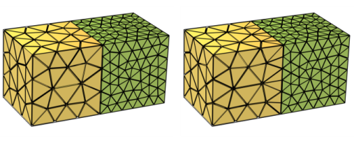
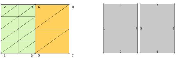
Import node if the imported mesh file contains a mesh of assembly type. Regardless of its origin, an assembly type of mesh defines several disconnected components with duplicated boundaries, edges, and points where the components are touching. The boundary meshes at touching surfaces between two parts do not need to define geometrically matching mesh vertices and elements. The image to the left in
Figure 8-1 shows a
nonmatching assembly mesh with two disconnected components. The exploded view to the right shows that the two components are indeed disconnected. The mesh contains 21 mesh vertices and 20 triangle elements, 2 domains (indicated by yellow and green colors), 8 edges, and 8 points.
To connect the physics in disconnected components, set up Identity Boundary Pairs and add pair boundary conditions in the physics interfaces. See
About Identity and Contact Pairs for more information. Alternatively, if you want to connect the meshes (and avoid setting up pairs), use a
Merge Entities operation (supported in 3D only) to merge the boundaries of the disconnected components.
When importing nonconforming mesh data, the
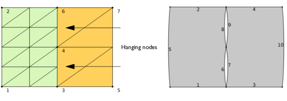
Import operation will typically create edge and boundary elements of the mesh edges and boundaries corresponding to each nonconformity in the mesh, since these mesh edges and boundaries are typically only adjacent to one element each. In
Figure 8-2, the image to the left shows the result after importing nonconforming mesh data, with so-called
hanging nodes. The mesh contains 18 mesh vertices and 20 triangle elements, compared to the assembly mesh in
Figure 8-1 which contains 21 mesh vertices. The resulting domains are connected in points 3, 4, and 6 with slit-like holes between the domains, as seen in the exploded view in the right image. Note that the mesh gets 2 domains (indicated by color), 10 edges, and 7 points.
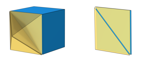
Import of nonconforming mesh data with so called hanging edges results in an error. A hanging edge appears when two triangles (yellow mesh faces to the right in
Figure 8-4) coincide with a quad (blue mesh face) with which they share mesh vertices.