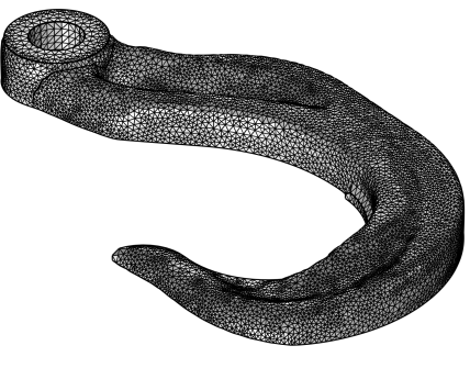
Use an Import node (

) to import mesh data from a
Filter or
Partition dataset. You can import mesh data from any simulation results. To position, rotate, and scale the mesh, use one or several
Transform attributes.

To import additional meshes, add another Import node. Then COMSOL Multiphysics adds the elements of the newly imported mesh to the existing mesh.
In the Source list, choose
Dataset to import the visualization mesh of a Filter or Partition dataset. This option is only available if there is at least one
Filter or
Partition node under
Datasets in
Results. Then, select a Filter or Partition dataset from the
Dataset list below.
In 2D and 3D, it is possible to import the result of a Filter or
Partition dataset evaluation. An example of where import of a dataset is used is when setting up a verification study for topology optimization results.
Select the Import selections check box (selected by default) to also import the selections defined by the component corresponding to the dataset. If you choose to import these selections, they will appear in the
Domain Selections,
Boundary Selections,
Edge Selections, or
Point Selections sections, depending on space dimension and the entity level for the imported selections. You can use the imported selections, for example, to add as a selection to a dataset or plot during postprocessing. See also
Entity Selections below.
In 3D, select the Import domain elements check box to import volumetric elements, such as tetrahedrons, hexahedrons, prisms, and pyramids. Clear this check box to only import boundary elements. The default is OFF when
Source is set to
Dataset. Domain mesh elements can only be imported if the result that the dataset is evaluated on is defined on a domain mesh.
If the Detect planar faces check box (3D) or the
Detect straight edges check box (2D) is selected (both are selected by default), the mesh import detects (approximately) planar faces or straight edges, respectively. The minimum size of a straight or planar boundary entity, relative to the entire boundary, can be set using the
Minimum relative length field (2D) and
Minimum relative area field (3D). The maximum accepted angle (in degrees) between elements for a boundary to be considered straight or planar can be set using the
Maximum deviation angle field. If the
Detect adjacent fillet faces check box (3D) is selected, the algorithm also searches for adjacent groups of boundary elements that form cylindrical faces.
If the Detect planar edges check box is selected (it is selected by default), the mesh import detects (approximately) planar edges. The
Detection parameter specifies to which extent the operation searches for planar edges. Use the slider to tune the detection level, where
Strict means that only fully planar edges are searched for, and
Tolerant means that the algorithm searches for planar edges with a wider tolerance. You can also enter the parameter value directly as a value between 0 (strict) and 1 (tolerant).
If the Detect straight edges check box is selected (it is selected by default), the mesh import detects (approximately) straight edges. The
Detection parameter specifies to which extent the operation searches for straight edges. Use the slider to tune the detection level, where
Strict means that only fully straight edges are searched for, and
Tolerant means that the algorithm searches for straight edges with a wider tolerance. You can also enter the parameter value directly as a value between 0 (strict) and 1 (tolerant).
From the Minimum edge length list, choose one of the following options:
Automatic (the default),
Relative, or
Absolute to specify the minimum required length of an edge to be detected. If you select
Relative, specify a minimum relative length in the
Minimum relative length field that appears, and if you select
Absolute, specify a minimum absolute length in the
Minimum absolute length field that appears.
The sections Domain Selections,
Boundary Selections,
Edge Selections, and
Point Selections appear after building the
Import operation. The selections are generated during the import based on selections defined in the source. In the
Name column, the name of each selection appears. For import of mesh data from results, each name is by default the name of the selection in the original geometry or mesh that appears in the
Name in source column. Select the name in the
Name column to highlight the selection in the
Graphics window. You can change the name of a selection by editing the corresponding table entry in the
Name column. Note that not all of these selection sections are available for all space dimensions.

