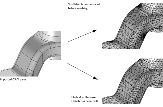
The operation Remove Details automatically finds and removes small details from the finalized geometry, that is the geometry after the
Form Union or
Form Assembly node has been built (see
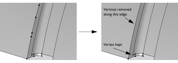
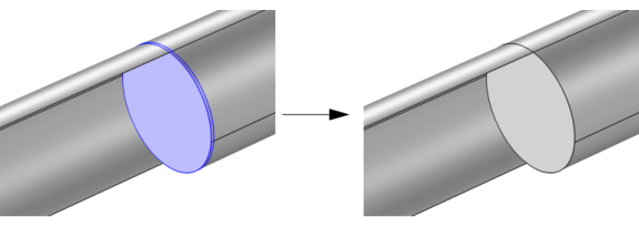
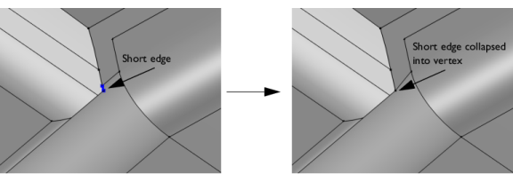
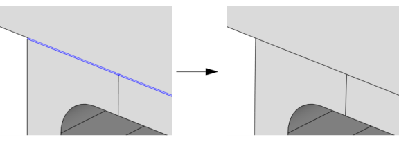
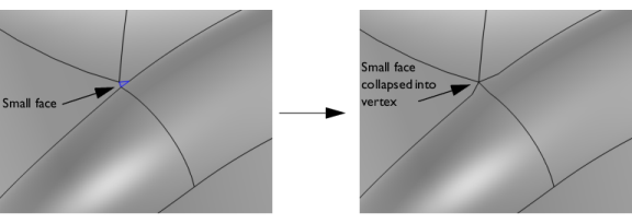
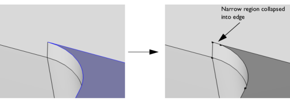
Figure 7-43). Small details include vertices with continuous tangent, short edges, small and narrow (sliver) faces, narrow face regions, and thin domains, which may all increase the number of mesh elements significantly. This, in turn, will lead to higher memory consumption. Small details may also influence the quality of the mesh elements, which may affect the possibility to reach a converged solution. Use
Remove Details to be in control of where finer mesh is created by removing small details not needed for the simulations. Then, set finer mesh size settings only in regions of importance for the accuracy of the solution.
The Remove Details operation acts on the finalized object and can therefore detect and remove small details created when misaligned objects are united, for example, unintended overlap domains created by slightly overlapping objects. Details are removed by automatically generating a sequence of virtual operations, which are organized in passes with increasing tolerances to remove larger and larger details with each pass. The sequence always ends with a cleanup of edges and vertices.
A geometry may contain details of various sizes which may require different tolerances to remove. Also, some details, even though small, may be important for the simulation results. In these cases, add several Remove Details operations, active on the entire geometry or a selection of entities, and each with its own unique settings. Add manual virtual operations in addition to one or several
Remove Details operations, as well as edit the sequence of operations automatically generated by
Remove Details. For details about available virtual operations, see links below the
Information section.
To add a Remove Details node to a geometry sequence, from the
Virtual Operations menu in the context menu when right-clicking a 3D
Geometry node or directly from the
Geometry ribbon toolbar, choose
Remove Details (

). The
Settings window contains the following sections:
The default in the Mode of operation list is
Automatic. Typically, use the automatic mode first. The
Remove Details operation generates and builds a local sequence of virtual operations. You can then switch to
Manual if needed to inspect the added virtual operations, fine-tune, and add more such operations. When you have built the
Remove Details node and the
Mode of operation list is set to
Manual, the created virtual operations are available as subnodes to the
Remove Details node. Alternatively, right-click the
Remove Details node and choose
Edit Generated Sequence (

). You can also then right-click the
Remove Details node to add more virtual operations. If you want to restore the generated sequence of virtual operations, choose
Reset to the Generated Sequence (

) from the
Remove Details node’s context menu.
The default is to remove small details from the entire geometry. From the Entities list, choose
Selection instead of
Entire geometry to make a selection of entities for which you want to remove small details.
If you choose Selection, the
Geometric entity level list appears with the options
Domain (the default),
Boundary, and
Edge. If the geometry sequence includes user-defined selections, you can choose one of them from the
Selection list; otherwise, or if you choose
Manual from the
Selection list, select entities from the
Graphics window or by pasting selections into the list of selected entities.
From the Detail size list, choose
Automatic (the default),
Relative, or
Absolute. If you choose
Relative the
Maximum relative size field appears. The default relative tolerance used is 0.001 which is relative to the length of the longest edge of the selection’s bounding box. If you select
Absolute, the
Maximum absolute size field appears. The default tolerance used is 0.001 times the longest edge of the geometry’s bounding box. When you build this feature, the
Maximum relative size and the
Maximum absolute size are set to the values that are used, which can be useful when you have set
Detail size to
Automatic.
The values in the Continuous tangent tolerance field (default value: 5 degrees) specifies the maximum allowed angular tangent deviation across a vertex or edge to be ignored.
This section contains information about the removed details: In the Type of removal column, the types of details that have been removed are listed. In the
Removed entities column, the number of entities for each type of remove operation is listed.
Click Build Selected (

) (or press F7) to build the geometry up to and including this node, click
Build Preceding (

) (or press F6) to build the geometry up to the node preceding this node, or click
Build All (

) (or press F8) to build all nodes in the geometry sequence.