Form Composite Faces
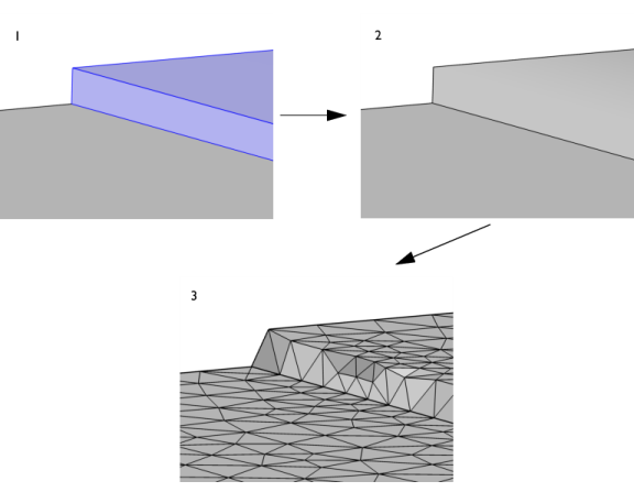
The operation forms a composite face for each connected face component (of manifold type) of the selected faces by ignoring the edges between the faces, as shown in Figure 7-22. By default, the vertices adjacent to the ignored edges are also ignored to form composite edges. It is possible to include several non-connected groups of faces in the same operation, as seen below.
Figure 7-22: Forming composite faces of the selected faces highlighted in blue. As seen in the image to the left, it is possible to select several non-connected groups of faces in the same Form composite faces operation.
It is recommended to keep edges in sharp corners of importance to the result. When a composite face is meshed, all mesh vertices are located on the face, but there is no guarantee that there will be mesh vertices on the ignored edge. For example, forming a composite face of two planar faces in a 90 degree angle, some of the created triangular elements may not coincide with any of the original faces, as shown below.
Figure 7-23: Possible effect of removing an edge in a sharp corner. 1. Two faces positioned in a 90 degree angle are selected (highlighted in blue) as input to the Form Composite Faces operation. 2. Resulting geometry after the edge connecting the two faces is removed. 3. This has the effect that the mesh elements do not have to respect this sharp corner, as shown here.
Tidying up a geometry to remove small and narrow faces gives the mesh algorithm more freedom to create a good quality mesh. An alternative is to use the Ignore Edges operation. The Remove Details operation provides a fully automated way to find sliver faces and form composite faces.
To use the operation, in the Geometry toolbar, from the Virtual Operations menu (), select Form Composite Faces (). Then enter the properties of the operation using the following sections:
Input
Select the faces that you want to composite in the Graphics window. They then appear in the Faces to composite list. If the geometry sequence includes user-defined selections above the Form Composite Faces node, choose Manual to select faces, or choose one of the selection nodes from the list next to Faces to composite.
Click the Active button to toggle between turning ON and OFF the Faces to composite selections.
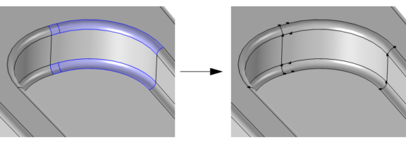
Use the Ignore adjacent vertices check box to also remove the ignorable vertices on the boundary of each resulting composite face. Keeping the adjacent vertices preserves the edge partitioning while forming composite faces, as shown in Figure 7-24.
Figure 7-24: The same faces selected as in Figure 7-22, highlighted in blue, but with the check box Ignore adjacent vertices cleared. The image on the right hand side shows that the vertices have been preserved along the edges of the resulting composite faces.
Mesh Control
Use the Keep input for mesh control check box to specify that the selected faces are composed in the geometry but the edges are available individually when you build the mesh. See also Mesh Control Edges.
Virtual Operations on a Wheel Rim Geometry: Application Library path COMSOL_Multiphysics/Meshing_Tutorials/wheel_rim
With the Structural Mechanics Module, see Submodel in a Wheel Rim: Application Library path Structural_Mechanics_Module/Tutorials/rim_submodel
With the Acoustics Module, see Wax Guard Acoustics: Transfer Matrix Computation: Application Library path Acoustics_Module/Tutorials,_Thermoviscous_Acoustics/wax_guard_acoustics
With the RF Module, see Branch-Line Coupler: Application Library path RF_Module/Couplers_and_Power_Dividers/branch_line_coupler