Ignore Edges
The operation removes the selected edges that are either isolated, adjacent to precisely two faces (3D), or are located between two domains (2D). Edges are removed by ignoring them. The resulting larger faces are denoted composite faces.
Figure 7-25: Ignoring the selected edges, highlighted in blue. The resulting geometry has larger composite faces. The vertices adjacent to the ignored edges are automatically ignored.
It is recommended to keep edges in sharp corners of importance to the result. When a composite face is meshed, all mesh vertices are located on the face, but there is no guarantee that there will be mesh vertices on the ignored edge. For example, ignoring an edge connected to two planar faces in a 90 degree angle, some of the created triangular elements may not coincide with any of the original faces, as shown below.
Figure 7-26: Possible effect of removing an edge in a sharp corner. 1. An edge connected to two faces positioned in a 90 degree angle is selected to be ignored (highlighted in blue). 2. Resulting geometry after the edge is removed. 3. This has the effect that the mesh elements do not have to respect this sharp corner, as shown here.
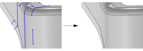
Tidying up a geometry to remove small and narrow faces gives the mesh algorithm more freedom to create a good quality mesh. An alternative is to use the Form Composite Faces operation. The Remove Details operation provides a fully automated way to find sliver faces, small faces and narrow face regions and uses, among others, the Ignore edges operation to form composite faces.
To use the operation, in the Geometry toolbar, from the Virtual Operations menu (), select Ignore Edges (). Then enter the properties of the operation using the following sections:
Input
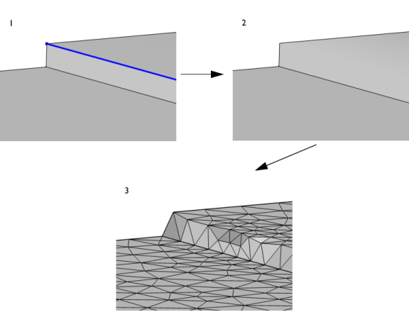
Select the edges that you want to ignore in the Graphics window. These then appear in the Edges to ignore list. If the geometry sequence includes user-defined selections above the Ignore Edges node, choose Manual to select edges, or choose one of the selection nodes from the list next to Edges to ignore.
Click the Active button to toggle between turning ON and OFF the Edges to ignore selections.
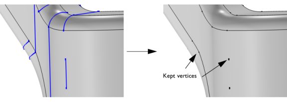
Use the Ignore adjacent vertices check box to also remove the ignorable start and end vertices of the edges.
Figure 7-27: The same edges selected as in Figure 7-25, highlighted in blue, but with the Ignore adjacent vertices check box cleared. The right image shows that the vertices representing the start and endpoints of the edges have been preserved. The arrows in the image on the right hand side indicate two of the vertices that has been kept.
Mesh Control
Use the Keep input for mesh control check box to specify that the selected edges disappear from the geometry but become available when you build the mesh. You can, for example, use mesh control edges to control the element size inside a domain or to partition the geometry to use a mapped mesh. See also Mesh Control Edges.
Swept Meshing of a Bracket Geometry: Application Library path COMSOL_Multiphysics/Meshing_Tutorials/bracket_swept_mesh
Shell Diffusion in a Tank: Application Library path COMSOL_Multiphysics/Equation_Based/shell_diffusion
Submodeling Analysis of a Shaft: Application Library path COMSOL_Multiphysics/Structural_Mechanics/shaft_submodeling
Tuning Fork: Application Library path COMSOL_Multiphysics/Structural_Mechanics/tuning_fork