Forming Composite Edges and Faces by Ignoring Vertices and Edges
This example of how to use virtual geometry operations shows how to use the Ignore Vertices operation (or the Form Composite Edges operation) to remove a very short edge and how to use the Ignore Edges operation (or the Form Composite Faces operation) to prepare the geometry for swept meshing.
Geometry 1
1
Add a 3D Component, either when Creating a New Model or adding The Component Node.
2
In the Home toolbar, click Import ().
3
In the Settings window under Import, select COMSOL Multiphysics file from the Geometry import list.
4
Click Browse.
5
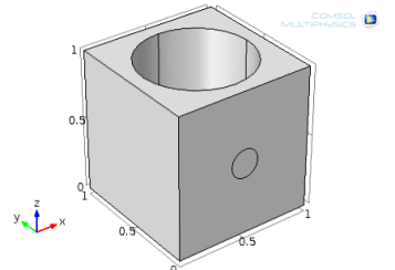
In the COMSOL installation directory navigate to the folder applications/COMSOL_Multiphysics/Meshing_Tutorials and double-click virtualgeom_demo_1.mphbin.
6
Click Import. In the Home toolbar, click Build All ().
The imported geometry displays in the Graphics window.
Mesh 1
In the Model Builder, click the Mesh node. In the Mesh toolbar, click Build All ().
The resulting mesh displays in the Graphics window.
A Warning node () is added under Mesh 1 indicating that there is a very short edge in the geometry. Use the Zoom Box button () and the Zoom to Selected button () in the Graphics toolbar to locate this edge.
Eliminate the short edge by ignoring the vertex between this edge and its adjacent longer edge.
Geometry 1
Ignore Vertices 1
1
In the Geometry toolbar, from the Virtual Operations menu, select Ignore Vertices ().
2
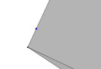
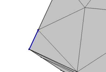
In the Graphics window click to select Point 3.
3
Click Build Selected ().
Mesh 1
In the Model Builder, click Mesh 1 and in the Settings window, click Build All (). The mesh displays in the Graphics window.
The geometry’s domain is well suited for swept meshing.
Swept 1
1
In the Mesh toolbar, click Swept ().
2
In the Settings window for Swept, click to expand the Source Faces section.
3
The Active button is by default. In the Graphics window click to select Boundary 3. Or click the Paste button () and enter 3.
4
Click to expand the Destination Faces section. The Active button is by default. Click to select Boundary 4.
Size
1
In the Model Builder, click the Size node ().
2
In the Settings window for Size under Element Size, choose Finer from the Predefined list.
3
Click the Build All button ().
4
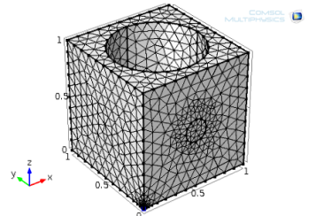
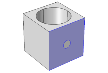
A COMSOL Error window opens indicating it Failed to create swept mesh for domain. Click OK to close the window. The COMSOL Multiphysics software fails to create a swept mesh due to the circular imprint on one of the linking faces of the sweep.
Use the Ignore Edges operation to remove this imprint.
Geometry 1
Ignore Edges 1
1
In the Geometry toolbar, from the Virtual Operations menu, select Ignore Edges ().
2
In the Graphics window, select Edges 14 and 15. Or click the Paste button and enter 14,15.
The Ignore adjacent vertices check box is selected by default so that the vertices of the imprint disappear as well.
3
Click the Build Selected button ().
Mesh 1
Click the Mesh 1 node and click Build All () in the Settings window.
The swept mesh displays in the Graphics window.
Geometry 1
Disable
1
In the Model Builder, right-click Ignore Edges 1 and choose Disable ().
2
Click Ignore Vertices 1 and press F3. This also applies the Disable command.
Form Composite Edges 1
1
In the Geometry toolbar, from the Virtual Operations menu, select Form Composite Edges ().
2
3
Click the Build Selected button ().
Form Composite Faces 1
1
In the Geometry toolbar, from the Virtual Operations menu, select Form Composite Faces ().
2
3
Click the Build Selected button ().
Mesh 1
Click the Mesh 1 node and click Build All () in the Settings window.