Ignore Vertices
The operation removes selected vertices that are isolated or are adjacent to precisely two edges. All edges in the geometry must have distinct start and end points. The software will ensure this by preserving or inserting extra vertices on the composite edges, if necessary.
Figure 7-30: The vertices selected to be removed by the Ignore vertices operation, highlighted in blue. The vertices connected to only two edges have been removed, resulting in longer composite edges. One vertex is still kept (indicated by arrow in right image) as it is connected to more than two edges.
It is recommended to keep vertices in sharp corners of importance to the result. When a composite edge is meshed, all mesh vertices are located on the edge but there is no guarantee that there will be a mesh vertex on the ignored vertices which, for example, means that if you ignore a vertex between two straight edges that are not collinear there can be one edge element that does not coincide with any original edge, as shown below.
Figure 7-31: Possible effect of removing a vertex in a sharp corner. 1. A vertex connected to two edges selected to be ignored, highlighted in blue. 2. Resulting geometry after the vertex is removed. 3. This has the effect that the mesh elements do not have to respect this sharp corner, as shown here.
An alternative is to use the Form Composite Edges operation. The Remove Details operation provides a fully automated way to find and remove isolated vertices and vertices adjacent to two edges. The evaluation is based on an angle criterion to only remove vertices if the tangent is considered to be continuous.
To use the operation, in the Geometry toolbar, from the Virtual Operations menu (), select Ignore Vertices (). Then enter the properties of the operation using the following sections:
Input
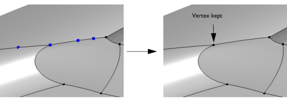
Select the vertices (points) that you want to ignore in the Graphics window. These then appear in the Vertices to ignore list. If the geometry sequence includes user-defined selections above the Ignore Vertices node, choose Manual to select vertices, or choose one of the selection nodes from the list next to Vertices to ignore.
Click the Active button to toggle between turning ON and OFF the Vertices to ignore selections.
Mesh Control
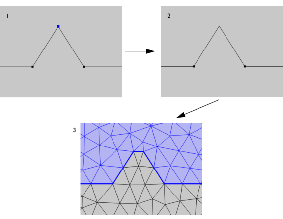
Use the Keep input for mesh control check box to specify that the selected vertices disappear from the geometry but become available when you build the mesh. You can, for example, use a mesh control vertex to control the element size inside a domain. See also Mesh Control Vertices.
With the Heat Transfer Module, see Parameterized Roller Shutter, Preset Model: Application Library path Heat_Transfer_Module/Buildings_and_Constructions/roller_shutter_thermal_performances_preset
With the RF Module, see Car Windshield Antenna Effect on a Cable Harness: Application Library path RF_Module/EMI_EMC_Applications/car_emiemc
With the Acoustics Module, see Loudspeaker Driver — Transient Analysis: Application Library path Acoustics_Module/Electroacoustic_Transducers/loudspeaker_driver_transient
With the Electrodeposition Module, see Electrodeposition on a Resistive Patterned Wafer: Application Library path Electrodeposition_Module/Tutorials/resistive_wafer
With the ECAD Import Module, see the documentation for Importing and Meshing a PCB Geometry from an ODB++ Archive: Application Library path ECAD_Import_Module/Tutorials/pcb_import