Form Composite Domains
The operation forms a composite domain for each connected domain component of the selected domains by ignoring the boundaries between the domains., see Figure 7-19. This means that it is possible to include several non-connected groups of domains in the same operation.
Figure 7-19: An object that extends into another object results in a thin disk-shaped domain, highlighted in green, after Form Union. By forming a composite domain the thin domain becomes part of one of its neighbors, in this case the domain highlighted in blue. Note that one face is hidden for better visibility.
Thin domains can require a very fine mesh to be well resolved. Forming a composite domain of the thin domain with a neighboring domain will remove the thin domain and therefore the need for a fine mesh. The same result can be achieved by using the Ignore Faces (3D) and Ignore Edges (2D). The Remove Details operation provides a fully automated way to find and remove thin and small domains.
To use the operation, in the Geometry toolbar, from the Virtual Operations menu (), select Form Composite Domains ( or ). Then enter the properties of the operation using the following sections:
Input
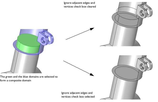
Select the domains that you want to composite in the Graphics window. They then appear in the Domains to composite list. If the geometry sequence includes user-defined selections above the Form Composite Domains node, choose Manual to select domains, or choose one of the selection nodes from the list next to Domains to composite.
Click the Active button to toggle between turning ON and OFF the Domains to composite selections.
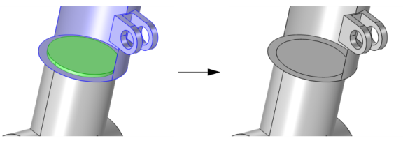
Use the Ignore adjacent vertices (2D) or Ignore adjacent edges and vertices (3D) check box (default selected) to also remove the ignorable vertices (and edges in 3D) on the boundary of each resulting composite domain. In 3D, clearing the check box leaves edges and vertices adjacent to the faces that have been removed.
Figure 7-20: Forming a composite domain of the domains highlighted in green and blue. Note that one face of the blue domain is hidden for visibility. With the Ignore adjacent edges and vertices check box cleared the edges and vertices of the ignored faces are kept inside the geometry (upper-right image). With this check box selected the edges and vertices are automatically removed (lower-right image).
Mesh Control
Use the Keep input for mesh control check box to specify that the selected domains are composed in the geometry but are available individually when you build the mesh. This gives you more control of the meshing. A well partitioned geometry is more efficient to mesh and can, for example, make it possible to create a high quality hexahedral mesh through the sweep operations. See also Mesh Control Domains.
Virtual Operations on a Wheel Rim Geometry: Application Library path COMSOL_Multiphysics/Meshing_Tutorials/wheel_rim
With the Heat Transfer Module, see Power Transistor: Application Library path Heat_Transfer_Module/Power_Electronics_and_Electronic_Cooling/power_transistor
With the Acoustics Module and Structural Mechanics Module, see Ground Motion After Seismic Event: Scattering off a Small Mountain: Application Library path Structural_Mechanics_Module/Elastic_Waves/ground_motion_seismic_event
With the CFD Module, see Flow in a Hydrocyclone: Application Library path CFD_Module/Single-Phase_Flow/hydrocyclone
With the Acoustics Module, seeUltrasound Flowmeter with Generic Time-of-Flight Configuration: Application Library path Acoustics_Module/Ultrasound/ultrasound_flow_meter_generic