Mesh Control Domains
Use Mesh control domains for precise control of the mesh in specific regions of the geometry, without affecting the geometry used for assigning physics.
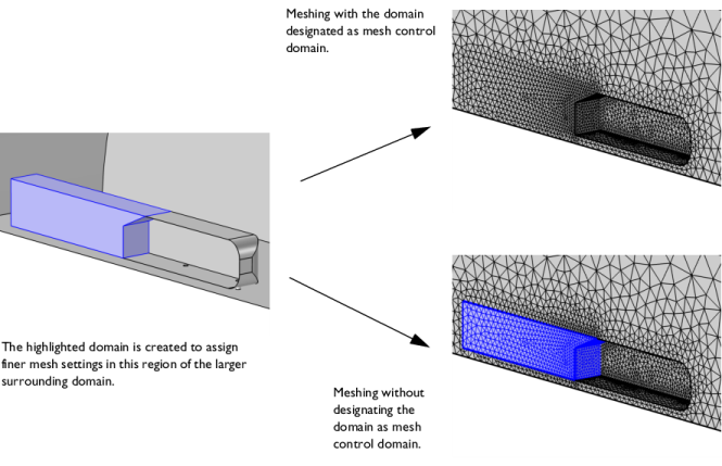
To fully resolve the gradients in a field in certain regions of a domain, a finer mesh may be required. One way to avoid refining the mesh in the entire domain, is to partition it, then assign a finer mesh size to the domain created by the partitioning, as shown in Figure 7-35. By designating the created domain as a mesh control domain, it will only be visible in mesh mode, and only before the mesh is generated. As soon as the mesh is built inside the mesh control domains and adjacent domains, the faces and edges adjacent to the mesh control domains are removed.
Figure 7-35: Domain highlighted in blue is designated as a mesh control domain, which means that the faces of this domain are removed and are only available when building the mesh. The image on the right hand side shows the geometry after the Mesh control domains operation has been built, which is the geometry displayed in physics settings. The bottom image shows the resulting mesh where the faces have been removed.
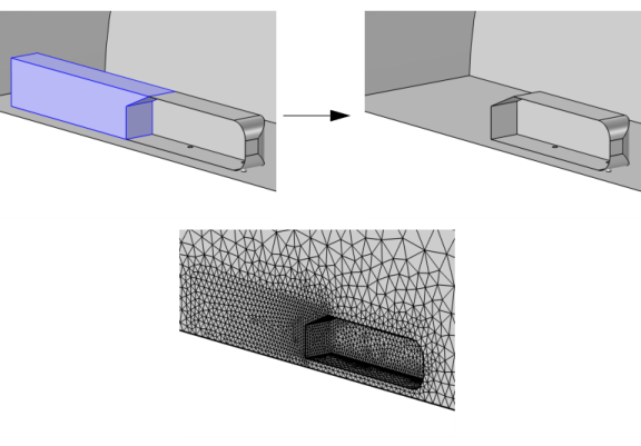
The operation removes the selected domains by composing them with adjacent domains as shown in Figure 7-35 and Figure 7-36. The faces (3D only) and edges become available when you build the mesh. This makes it possible to partition a domain to prepare it for swept meshing, or to control the mesh size in a specific region, without modifying the geometry that appears when assigning physics settings.
An advantage of working with mesh control domains is that when the faces have been removed, the mesher can move mesh vertices to make a smoother the size transition across the removed entities (see Figure 7-36). This behavior is controlled by the settings in the section Control Entities of the mesh operation used to mesh the domains.
Figure 7-36: Comparing meshes where the Mesh control domains has been used vs. not used. A smaller domain added for the purpose of resolving the mesh in a region with steeper gradients (highlighted in blue in the image to the left). Designating the domain as a mesh control domain removes the faces of the selected domain and compose it with the adjacent domain (upper right image). The lower right image shows the mesh if the domain is not marked as a mesh control domain. This means that the face, edge, and domain partitioning are preserved. Compare the meshes on the right-hand side to see the effect of smoothing the size transition across removed mesh control entities.
To use the operation, in the Geometry toolbar, from the Virtual Operations menu (), select Mesh Control Domains (). Then enter the properties of the operation using the following sections:
Input
Select the domains that you want to use for mesh control in the Graphics window. They then appear in the Domains to include list. If the geometry sequence includes user-defined selections above the Mesh Control Domains node, choose Manual to select domains, or choose one of the selection nodes from the list next to Domains to include.
Click the Active button to toggle between turning ON and OFF the Domains to include selections.
With the CFD Module, see Displacement Ventilation: Application Library path CFD_Module/Nonisothermal_Flow/displacement_ventilation
With the Structural Mechanics Module, see Cylinder Roller Contact: Application Library path Structural_Mechanics_Module/Verification_Examples/cylinder_roller_contact
With the Nonlinear Structural Mechanics Module, see Snap Hook: Application Library path Nonlinear_Structural_Materials_Module/Plasticity/snap_hook
With the Fatigue Module, see Notch Approximation to Low-Cycle Fatigue Analysis of Cylinder with a Hole: Application Library path Fatigue_Module/Strain_Based/cylinder_with_hole_plastic