Mapped
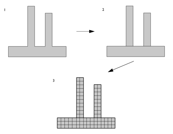
The operation creates a structured quadrilateral mesh on boundaries in 3D and domains in 2D, as shown in Figure 8-54. The Mapped () operation can also be used to remesh meshes that define their own geometric model, such as imported meshes in 2D and 3D.
Figure 8-54: A mapped mesh in a 2D domain of a flow duct (left). The image on the right hand side shows a mapped mesh on an L-shaped cross-section face (highlighted in blue) of a part of a shaft. The mapped mesh is swept through the 3D domain to arrive at a hexahedral volume mesh, using a Swept operation.
You can control the number, size, and distribution of elements using Size (only the Maximum element size parameter is used) and Distribution subnodes.
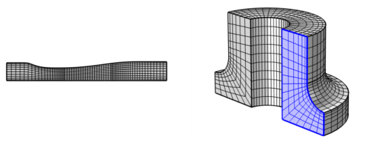
For a mesh that defines its own geometric model, use Mapped to remesh one or several faces. The mesh vertices are placed on a curved surface approximation of the input mesh.
Only surface meshes with first-order elements can be remeshed. Clear the Import domain elements check box in the mesh Import node to import only boundary elements. Select check box Import as linear elements to ignore second-order mesh data. See Importing Meshes for more information.
See The Mesh Node to learn more about meshes that define their own geometric model.
To create a mapped quadrilateral mesh for each domain (boundaries in 3D), the mapped mesher maps a regular grid defined on a logical unit square onto each domain. The mapping method is based on transfinite interpolation. The settings in the Size and Distribution nodes used by a Mapped node determine the density of the logical meshes. For the mapping technique to work, the opposite sides of each logical unit square must be discretized by the same number of edge elements.
By default, the relationship between the four sides of the logical unit square and the boundaries around a domain is based on a criterion related to the sharpest angle between boundaries. If you want to control this relationship, right-click the Mapped node to add an Edge Groups subnode.
2D Mapped Mesh Geometry
For the 2D mapped meshing technique to work properly, the geometry must be reasonably regular. The following conditions must be satisfied:
For a geometry that does not initially meet these criteria, it is usually possible to modify it so that a mapped mesh is generated, for example, by partitioning it into simpler domains, as shown in Figure 8-55. Consider using Mesh Control Operations to hide the added edges and points from the physics view.
Figure 8-55: Partitioning a domain into smaller rectangular domains in order to build a mapped mesh. 1.Original domain where a mapped quad mesh cannot be created. 2. Partition the domain into three rectangular domains. 3. Resulting mapped mesh in the partitioned geometry.
To create a mapped quadrilateral mesh, select boundaries (3D) or domains (2D) in the Graphics window, then:
From the Mesh toolbar, choose Mapped from the Boundary menu () (3D components) or click the Mapped () button (2D components).
Right-click a Mesh node and choose Mapped (). For 3D models, this is selected from the More Operations menu.
Then enter the properties for the mapped meshing operation using the following sections:
Entity Selection
Define the boundaries (3D) or domains (2D) where you want to create a mapped quad mesh. Choose the level of the geometry from the Geometric entity level list:
Choose Remaining to specify mapped quad mesh for remaining, unmeshed domains.
Choose Entire geometry to create a mapped quad mesh in the entire geometry.
Choose Boundary (3D) or Domain (2D) to specify the geometric entities for which you want to create a mesh. Choose Manual from the Selection list to select the boundaries or domains in the Graphics window, choose a named selection to refer to a previously defined selection, or choose All boundaries (3D) or All domains (2D) to select all boundaries or all domains.
Control Entities
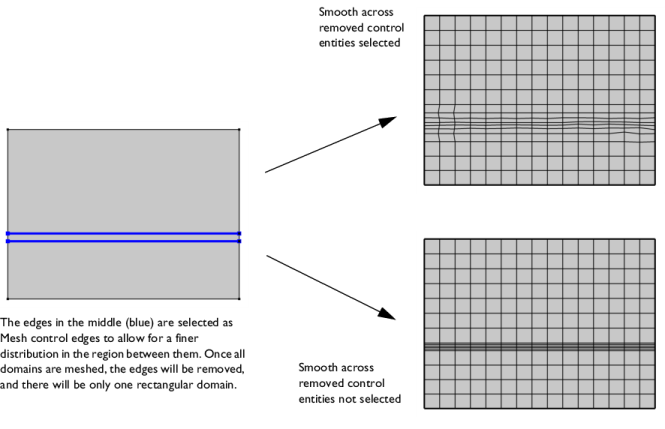
Select the Smooth across removed control entities check box to smooth the transition in element size across removed Controlling the Mesh Size Using Mesh Control Entities. You can specify the number of smoothing iterations in the Number of iterations field. In the Maximum element depth to process field you can specify the maximum element depth for the mesh points to be smoothed.
Figure 8-56: Comparing meshes where Smooth across removed control entities has been used vs. not used. The two edges (highlighted in blue in left image) adjacent to the domain in the middle are designated as Mesh Control Edges. A finer distribution is set between the edges and when all domains are meshed, the edges are removed, leaving only one large rectangular domain. With the Smooth across removed control entities check box selected (upper right image), the mesher adjusts the sizes of the quad elements to get a smoother transition from large to small elements. Clear the check box to not adjust the mesh (lower right image).
Reduce Element Skewness
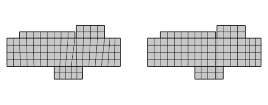
Select the Adjust edge mesh check box (cleared by default) to allow the mapped mesher to adjust the mesh on edges that are not already meshed and where no explicit distribution is applied in order to reduce the element skewness (see Figure 8-57 below).
Figure 8-57: Images showing the effect of the Adjust edge mesh setting. The default mapped mesh (left) has some skewed elements. Turning on the Adjust edge mesh setting results in quads with angles closer to 90 degrees (image to the right).
Advanced Settings
In this section you can choose between two different interpolation methods in the Interpolation method list. This specifies how the mapped meshing operation determines the positions of the interior mesh points. Select Automatic (default) to let the mapped meshing operation determine a suitable interpolation method automatically. In many cases, the interpolation methods give the same result. If you select Transfinite in 2D, the positions of the interior mesh points are determined by transfinite interpolation in the 2D parameter space of the corresponding surface. This method works best for faces with smooth surface parameterization. If you select Transfinite in 3D, transfinite interpolation is done in 3D to determine these positions. This method works best if the shape of the exterior edges represent the shape of the surface in a good way.
For an example of a 2D mapped mesh, see Tubular Reactor with Nonisothermal Cooling Jacket: Application Library path COMSOL_Multiphysics/Chemical_Engineering/tubular_reactor.
For an example of a 2D mapped mesh, see Flow Duct,
Application Library path Acoustics_Module/Aeroacoustics_and_Noise/flow_duct.
For an example of a mapped mesh in 3D, see Submodeling Analysis of a Shaft,
Application Library path COMSOL_Multiphysics/Structural_Mechanics/shaft_submodeling.