Controlling the Mesh Size Using Mesh Control Entities
The most straightforward way to control the mesh size in a part of a domain or on part of a boundary is to partition the geometry in such a way that a mesh Size can be assigned on the entity in question. However, the additional domain, face, or curve is typically not wanted when assigning materials and physics. Mark the additional entity as a mesh control entity to remove it from the view once it has been meshed.
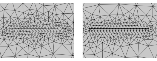
For example, add a rectangle inside a 2D domain to resolve the mesh inside the rectangle (see right image in Figure 8-14). Mark the resulting edges as a mesh control entity to remove it from the geometry when defining the physics and materials. An advantage is that the final mesh need not respect the mesh control edges exactly; it is used only to control element size and then the mesh is smoothed, as shown in the left image below.
Figure 8-14: Comparison of meshes when Mesh control entities is used vs. not used for the interior boundaries.
Another situation where mesh control entities are useful is when you need precise control of the mesh in certain regions of the geometry. In these regions you typically use a structured mesh with distribution nodes to control the mesh. In other regions of the geometry you can use an unstructured mesh.
Building a boundary layer mesh adjacent to an internal boundary means that the boundary layer mesh need to respect them. This may lead to low-quality elements at acute angles and even meshing failures. Mark internal boundaries that are not needed with respect to materials and physics as mesh control entities to give boundary layer mesher more freedom to move mesh nodes and construct a better mesh.