Structured Meshes
Compared to an unstructured mesh, the interior mesh vertices in a structured mesh are adjacent to the same number of elements.
Structured Triangle Meshes
You can create a structured triangular mesh on domains in 2D and on faces in 3D by using the Convert operation. There is an option to either introduce a centerpoint (shown in Figure 8-5), or a diagonal edge to quadrilateral elements.
Figure 8-5: A centerpoint is inserted in each quad element, resulting in a structured triangular mesh.
Mapped Meshes
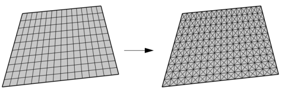
The Mapped mesher generates a structured mesh with quadrilateral elements (as shown to the left in Figure 8-5).
Swept Meshes
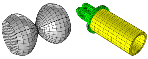
The Swept operation generates a structured mesh (at least in the direction of the sweep) with prism or hexahedral elements, as shown in Figure 8-6.
Figure 8-6: Swept meshes. The left image shows a hexahedral mesh. The image on the right hand side shows a tetrahedral mesh (green) combined with a swept prism mesh (yellow).
2D and 3D Boundary Layer Meshes
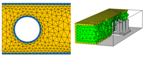
The Boundary Layers operation also generates a structured mesh. A boundary layer mesh has a dense element distribution in the normal direction along specific boundaries, integrating into an existing structured or unstructured mesh.
In 3D, the boundary layer mesh is a layered prism mesh (see the yellow prisms in Figure 8-7) or a hexahedral mesh, depending on whether the corresponding boundary-layer boundaries contain a triangular or quadrilateral mesh.
Figure 8-7: In 2D, the boundary layer mesh is always a quad mesh (blue in left image), while in 3D, the boundary layer elements can be either prism elements (yellow in right image) or hex elements.
This type of mesh is typically used for fluid flow problems in order to resolve the thin boundary layers along the no-slip boundaries. Boundary layer meshes can also resolve large temperature gradients close to heated surfaces subjected to sudden changes over time.