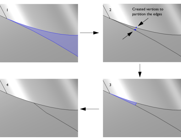
The Collapse face regions operation detects and removes narrow regions for a selection of faces. Narrow face regions is often the result of two edges meeting at a very sharp angle (see
Figure 7-17) and may cause mesh refinements or even meshing failure. The operation detects narrow regions based on a specified width tolerance. To remove a narrow regions, the edges adjacent to it are first partitioned by creating vertices. Then, an edge with a length according to the tolerance is created between the vertices to partition the face. Lastly, the sliver face created by the partitioning is collapsed into an edge, which leaves the original face with a less narrow region.
In some cases, an alternative to collapsing a narrow face region could be to remove the edges that cause the narrow region by using the Ignore Edges operation. The
Remove Details operation provides a fully automated way to find and remove narrow regions within a selection of boundaries or boundaries adjacent to a selection of domains.
To use the operation, in the Geometry toolbar, from the
Virtual Operations menu (

), select
Collapse Face Regions (

). You can also select it from the
Geometry node’s context menu’s
Virtual Operations submenu.
Select the faces for which you want to collapse narrow face regions in the Graphics window. They then appear in the
Faces list. If the geometry sequence includes user-defined selections above the
Collapse Face Regions node, choose
Manual to select faces, or choose one of the selection nodes from the list next to
Faces.
Click the Active button to toggle between turning ON and OFF the
Faces selections.
The Narrow regions tolerance controls how much of a narrow region to collapse. By default, it is set to
Automatic. The default tolerance used is 0.001 times the length of the longest edge of the geometry’s bounding box. For more control, select
Manual to enter a value in the
Maximum width field that appears. The default value is 0.001. The tolerance is the maximum width of a face region to be considered as narrow. If you build the operation with
Automatic and then switch to
Manual, the
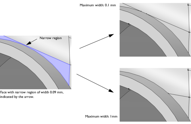
Maximum width field shows the value of the parameter that was used when the operation was built. A larger
Maximum width will detect wider regions than a smaller value. It will also collapse a larger portion of the face, as shown in
Figure 7-18.