About Selecting Geometric Entities
Throughout COMSOL Multiphysics there are many lists of selected geometric entities, all based on the same principle — pick domains, boundaries, edges, or points and use methods to add or remove these geometric entities to create selections that define, for example, the parts of the geometry where a material or boundary condition is active. Such lists appear in Settings windows for defining equations and material properties, boundary conditions, sources, mesh features, and other parts of the model’s design, and in the Variables node () definitions for variables that are not defined in the entire model.
All levels of geometry can be treated individually. You can add and remove 3D geometric entities (domains, boundaries, edges, or points) to selection lists in different ways, including buttons in the Graphics toolbar (The Graphics Window Toolbar Buttons and Navigation), using The Selection List Window, clicking directly on the geometry, or clicking buttons in the Settings window. You can also select entities in the list to then remove them from the selection, for example. Ctrl+A selects all entities in the list. Table 6-2 lists the buttons that display on every Settings window with a geometric entity selection list as displayed in Figure 6-6.
Figure 6-6: The selection list and toolbar on a physics node Settings window. The geometric entity level for the top Settings window is domains. The bottom Settings window is for a default boundary condition node where the selection cannot be changed, although a boundary can be overridden.
Figure 6-7: The Geometric entity level selection list and toolbar on a Settings window for Material (left) and the Settings window for Variables (right).
In The Graphics Window, the geometric entities are color highlighted as you make the selections, and you can lock the selections by turning off the active selection (at most one selection can be active at a time) or select Disable Mouse Selection ( in 3D) in the Graphics window toolbar.
The Geometric Entity Selection Sections
The name of the section where the list of selected geometric entities is managed depends on the geometric entity level. For example, Figure 6-6 displays a Domain Selection section.
Every geometric entity selection section also has an Active button to toggle between turning on or off selections for that node.
For physics nodes that are default nodes (see Physics Interface Default Nodes) the selection defaults to all geometric entities on the applicable level (all domains or all boundaries, for example, in Figure 6-6), and the Selection list is not active. You can add other nodes that override the default nodes for some or all entities. Those entities are then marked (overridden) in the selection list for the default node.
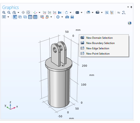
Geometric Entity Selection: For Materials and Variables nodes, where you first select the level (domain, boundary, and so on), from a Geometric entity level list. See Figure 6-7 for an example using the “Diagonal Mounting Detail of a Communication Mast” model.
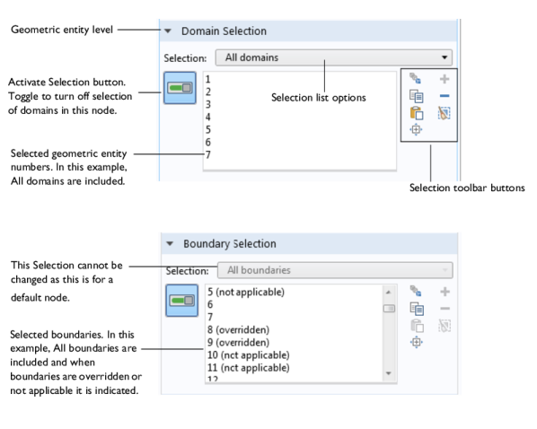
Domain Selection: For nodes that define, for example, material models, sources, and body loads in domains. See Figure 6-6 for an example.
Boundary Selection: For nodes that define, for example, boundary conditions.
Edge Selection: For nodes that define, for example, conditions and forces on edges. This is applicable to 3D models only.
Point Selection: For nodes that define, for example, point sources and point loads.
From the Selection list you can choose one of the following options:
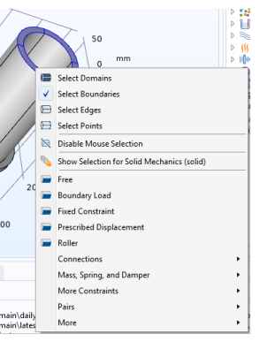
Manual (the default): Select the geometric entities directly in the Graphics window, using The Selection List Window, or using the Paste Selection button. See below for more information about those selection methods.
If you start by setting the Geometric entity level to Domain, and then select All domains, the Selection list displays all domains. If you make any changes to this list (for example, remove a domain) the Selection list reverts to Manual.
All domains, All boundaries, All edges, All points: Depending on the geometric entity level, you can choose one of these options to select all entities. See Figure 6-6 for example.
Defined named selections: Selection nodes added in the geometry sequence or under Definitions (as well as selections created from Boolean operations, for example) are available in the Selection lists for nodes that define model properties for the same geometric entity level. You can rename such selection nodes to better reflect what the selected entities represent. A named selection can consist of, for example, the domains where a volume force acts, the boundaries where an inflow occurs, or points that are grounded. Named selections are useful for reusing selections in a model component and to clearly indicate what parts of geometry that the selected entities include or represent. See Creating Named Selections.
In the lists of selected entities, (overridden) and (not applicable) can display next to the label (the number) of a selected entity. See Figure 6-6 and Physics Node Status for more information about these status indicators. There is also an Override and Contribution section in all physics nodes. It provides an overview of how the physics nodes and their selections interact. See Physics Exclusive and Contributing Node Types.
Pair Selection
If the geometry is an assembly you have access to specific pair conditions (typically on boundaries) that you choose from a Pairs submenu on the main physics nodes’ context menus. In the Settings window for such pair nodes, a Pair Selection section contains a list (initially empty) of the selected pairs (typically identity pairs). Select the pairs where you want to include by clicking the Add button () and choose the pairs to add from the list in the Add dialog box that opens; then click OK. The Boundary Selection section (or another standard selection section) is then not possible to modify and shows the entity numbers for the boundaries, for example, that the selected pairs include. See Identity and Contact Pairs.
See Table 6-3 for the many ways to select geometric entities using toolbar buttons, mouse click options, page settings, and keyboard shortcuts.
Right-Clicking to Select Geometric Entities and Add Physics Features
You can right-click anywhere in the Graphics window to define a preselection of some geometric entities and the add some physics feature with that selection. On the context menu, when a physics interface node is selected in the model tree, choose New Domain Selection, New Boundary Selection, New Edge Selection, or New Point Selection, depending on the domain level that you want to make a selection for (not all levels are available for all space dimensions).
Figure 6-8: Right-click in the Graphics window to create a new selection for some physics.
For the geometry in the figure above, which is taken from the Stiffness Analysis of a Communication Mast's Diagonal Mounting model in the COMSOL Multiphysics Application Library, say that you want to add a boundary load to the four bottom boundaries (faces). Then with a Solid Mechanics interface node selected, add a new boundary selection for those boundaries and then right-click and select Boundary Load from the context menu.
Figure 6-9: The context menu for adding a physics feature to the preselection (for Solid Mechanics).
A Boundary Load node is then added to the Solid Mechanics interface in the model tree with its selection being the four bottom boundaries. You are still in the preselection mode and can make a new boundary selection, for example. The added selection appears in yellow. If you want to add more boundaries to this Boundary Load mode, select them, and then right-click and choose Add to Boundary Selection for Boundary Load 2 (for example).
Figure 6-10: The added Boundary Load node’s Settings window and its selection highlighted in yellow.
By selecting the Show Selection for Boundary Load 2 (for example) item om the context menu, you can turn the yellow highlighting of that selection on and off. To activate the selection in the Settings window, turn on the Activate Selection button in the Settings window’s Boundary Selection setting, or move to another node in the tree and then back.
Settings Window Toolbar