Physics Exclusive and Contributing Node Types
The nodes for the physics interfaces and features are in a sequence, which acts like a macro that the software runs in a top-down order. Depending on the selection for each node, a node can totally or partially override, or shadow, a node earlier in the sequence. How the software treats these nodes depends on the relationship. There are two different types of nodes: exclusive and contributing (see Figure 3-8)..
Exclusive Nodes
The use of an exclusive node means that only one can be active for a given selection. That is, if you add another exclusive node (for example, an identical node) with the same selection, the first exclusive node is overridden and thus has no effect.
Typical exclusive nodes include model equations, initial values, and boundary conditions that are constraints, such as prescribed values for displacements, temperatures, pressures, and so on, or other Dirichlet-type conditions, including special variants of these such as ground conditions in electromagnetics and fixed constraints in structural mechanics. Also some boundary conditions that are not constraints but have a definitive meaning are exclusive nodes — for example, electric insulation, thermal insulation, and no-flow conditions. Depending on the selections for each node, an exclusive node can override another node partially. Nodes are exclusive only within their specific physics interface. When a node is selected in the Model Builder tree, nodes that are overridden by the selected node have a red arrow in the lower-left corner of the icon (), and nodes that override the selected node display a red arrow in the upper-left corner of the icon ().
Contributing Nodes
A contributing node means you can have more than one of these nodes with the same selection and that the software adds these together when evaluating the model. Typical contributing nodes are loads, fluxes, and source terms, where you can have more than one of each type that is active on the same domain or boundary, for example. The total effect is then a sum of each contributing node. When a node is selected in the Model Builder tree, the tree shows other nodes, which the current node contributes with, indicated using a yellow dot to the left of the icon (for example, in this boundary level icon ). See also Figure 3-8 for an example.
Order of Exclusive and Contributing Nodes
An exclusive node typically override all other nodes that share some common geometric entity and that appear above it in the list of nodes under a physics interface. Conversely, a contributing node can contribute with an exclusive node that appears above it. For example, in a heat transfer interface, a Temperature exclusive node overrides a Heat Flux contributing node defined above it (when defined on some common boundaries). If you switch the order of those nodes, so that the Heat Flux node appears below the Temperature node, it then contributes with the Temperature node. Because the Temperature node imposes a constraint on the temperature, the computed solutions are identical when evaluating the temperature. However, the contributing heat flux changes the reaction force of the temperature condition, which you can verify by integrating the reaction force on a boundary using the reacf operator, for example.
Listing Overrides and Contributions
If your preferences include showing the Override and Contribution section in the Settings windows for physics nodes, you can find the following information about how exclusive and contributing nodes interact in the model. Click the Show More Options button () and select the Override and Contribution in the Show More Options dialog box to display the information as in Figure 3-8 and described below.
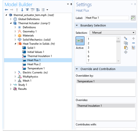
The Overridden by list contains the names of the nodes that the selected node is overridden by. The selected node is then overridden by these nodes at least partially, and the Selection list contains (overridden) for the geometric entities (boundaries, for example) where it is overridden. The nodes that the selected node is overridden by are indicated using a red arrow in the lower-left corner of the icon such as in this boundary level icon .
The Overrides list contains the names of the nodes that the selected node overrides (where the current node is active). The nodes that the selected node overrides are indicated using a red arrow in the upper-left corner of the icon such as in this boundary level icon .
The Contributes with list contains the names of the nodes that the selected node contributes with for at least some shared selection. The nodes that the selected node contributes with are indicated using a yellow dot to the left of the icon such as in this boundary level icon .
If a physics node is disabled locally in a study step using the Physics and Variables Selection section in the study step’s Settings window, the indications of overrides and contributions in the Model Builder are unchanged (but disabled physics nodes get an asterisk to indicate that their state has been changed in at least one study step). However, the local variables and physics tree in the study step’s Settings window displays the overrides and contributions taking the disabled nodes into account.
Figure 3-8: The Override and Contribution section lists other physics nodes that the selected node is overridden by, overrides, or contributes with.