You are viewing the documentation for an older COMSOL version. The latest version is
available here.
All study step Settings windows contain a
Physics and Variables Selection section, which you can use to control which physics interfaces (or even specific variables and physics nodes) to solve for. This can be useful for:
The Physics interface column contains the names of all true physics interfaces in the model. Some special auxiliary interfaces, notably
Optimization and
Sensitivity, are not shown when their dependent variables are controlled in other ways. The
Moving Mesh interface itself is also excluded, but instead there is a special entry with the same name for controlling the mesh motion in each component. This entry appears in the list as soon as you add features under
Definitions>Moving Mesh, or if your model contains any interface controlling the spatial frame, and the spatial frame uses dependent variables.
You can choose to not solve for one or more of the physics interfaces or the spatial frame by clicking the  button in the Solve for
 column (by default, a study solves for all physics interfaces). Those physics interfaces are then not solved for but can still provide values for the degrees of freedom (dependent variables) according to the settings for values of variables not solved for (see
Values of Dependent Variables). Click the button (

when the physics is deactivated) again to solve for the physics interface.
In the Discretization list you can specify which discretization to use. The default (and often the only) choice is
Physics settings, which means that the study uses the discretization from the main physics interface node’s settings. Changing it affects the discretization order used by this study. To add another discretization, use a separate
Discretization node in the physics interface. The leftmost column is usually empty but contains a warning (

) if the physics’ degrees of freedom are not solved for regardless of the setting in the
Solve for column. This can be the case if the physics interface is not compatible with the study step.
The Multiphysics couplings column contains the names of all multiphysics couplings in the model. You can choose to not solve for one or more of the multiphysics couplings by clicking the

button in the
Solve for column (by default, a study solves for all physics interfaces). If you clear the
Solve for button, any equations and dependent variables that the multiphysics coupling adds are not included, but the multiphysics coupling still affects the definition of variables.
If the model contains a Model Reduction study, there is also a
Reduced model column, where the
Reduced Model node that contains the reduced model appears. Select the
Store output dependent variables check box to store the output from the reduced model as dependent variables for postprocessing. This option is available if you have selected the
Add output dependent variables check box in the
Reduced Model node’s settings.
If reconstruction is included in the model reduction, you can choose a compatible reduced model to use for reconstruction under Reduced model for the physics interface that is to be reconstructed under
Reconstruction. This section is only available if the physics interface is not being solved for (the
Solve for check box is cleared in the
Physics interface section above). By default, this reduced model applies to all fields and states in the physics interface. If desired, it is possible to use different reconstruction for different fields and states by choosing another
Reduced Model node in the
Field and
State nodes.
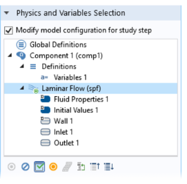
If the Modify model configuration for study step check box is selected, you can modify the model configuration by specifying which variables and physics features to include in the model that you solve. You can also control
Perfectly Matched Layers, Infinite Element Domain, and other features under
Component>Definitions as well as specifying which physics that manages which frame. The
Physics and Variables Selection section then contains a tree that is a copy that include the following parts of the model tree in the Model Builder (see
Figure 20-4):
|
•
|
Variables nodes under Component>Definitions for all Component branches.
|
|
•
|
Perfectly Matched Layer, Infinite Element Domain, and Scaling System nodes under Component>Definitions for all Component branches.
|
Click  Disable
 (or right-click to select from the context menu) to disable enabled nodes that are possible to disable. The contributions, conditions, or variables in a node that you disable are not included in the study when solving. You can also disable selected nodes by clicking the
Disable button (

) underneath the tree. A disabled node is unavailable in the tree. You can also right-click any applicable node in the model tree to select
 Disable in all studies
. That node is then disabled for all studies.
Click  Enable
 (or right-click to select from the context menu) to enable disabled nodes. The contributions, conditions, or variables in a node that you enable are included in the study when solving. You can also enable selected nodes by clicking the
Enable button (

) underneath the tree.
|
•
|
Not Applicable — for physics nodes that are not applicable for the study type in the study step. The item in the tree is not available.
|
An asterisk displays in the upper-right corner of nodes for which the state has been changed in the study step’s selection tree compared to the state in the Model Builder. In this example, under the Physics and Variables Selection section, a Transport in Diluted Species interface (

) is disabled (unavailable), provides no degrees of freedom (red dot in the lower-right corner), and has a change of state indicated by the asterisk. The asterisk means the Laminar Flow interface in the Model Builder is not disabled. Also see
Figure 20-4 for another example. In general, any variable or physics node in the Model Builder that is disabled in any study step gets an asterisk in the upper-right corner. For physics interfaces, this applies also when you have not selected the
Modify model configuration for study step check box and the physics interface is disabled in the
Solve for column in the
Physics and Variables Selection section.
The dynamic visual icon indicators for overridden and contributing nodes also appear in the tree in the Settings window for the study steps when you have selected the
Modify model configuration for study step check box in a study step’s
Settings window. When you select a physics node in the tree, the override and contribution icon indicators appear in the same way as in the Model Builder when you select a physics node, but if you disable any physics node in the study step’s tree, the icon indicators then show how the physics node overrides and contributes to the model when one of more physics nodes are disabled in the study step.
The following options are available for the main physics nodes under the Physics and Variables Selection tree. Right-click a node and select one of the following from the context menu or click the button beneath the tree (see
Figure 20-4). Selecting these options affects the entire physics interface. Select:
|
•
|
 Solve For Solve For (the default setting) to solve for the physics interface, including all enabled physics nodes and the contributions, constraints, and variables that are added. This is similar to the  button when you specify what physics interfaces to solve for without the selection tree. |
|
•
|
 Disable in Solvers Disable in Solvers to not solve for the physics interface but provide degrees of freedom (dependent variables) and other physics node variables using the settings for values of variables not solved for (see Values of Dependent Variables). |
|
•
|
 Disable in Model Disable in Model to fully disable a physics interface or node in the model. The physics interface or node does not contribute to the study and no variables, including the degrees of freedom (dependent variables), are included. |