About Highlighted Geometric Entities in the Graphics Window
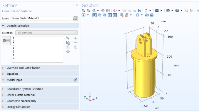
The Graphics window in the COMSOL Desktop highlights geometric entities at different stages of selection. A geometric entity is highlighted in red, blue, green, yellow, or with no highlight (gray) to indicate its status.
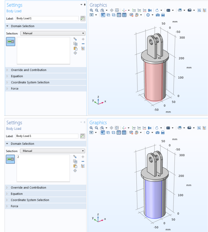
When assigning geometric entities to a node and you hover over that entity in the Graphics window, click once to add it to a selection list. See Figure 6-5 for an example. If you select the Require click in Graphics window to activate hovering check box under Selections on the Graphics and Plot Windows page in the Preferences dialog box, then you must first click once in the Graphics window before you can hover and click to select. See also Selection Colors below.
Blue
For geometric entities added to a selection. A geometric entity highlighted in blue is included in the list of selected entities for the specific node. See Figure 6-4 for an example.
Red
Hovering over or selecting unselected geometric entities. When you hover over a geometric entity that has not yet been added to a selection, or if you select such a geometric entity in The Selection List Window, it is highlighted in red to help you locate it on the Graphics window. See Figure 6-4 and Figure 6-5 for examples.
An entity highlighted in red is not yet added as a selection. Either click it in the Graphics window, or right-click the entity in the list or click the Add to Selection button in the Selection List window. The entity is then highlighted in blue to indicated that it has been added to the selection.
Green
Hovering over or selecting selected geometric entities. When you hover over a geometric entity that has already been added to a selection, or if you select such a geometric entity in the Selection List window (indicated by (selected) next to the entity number), it displays in green to indicate that it is included in the selection list. See Figure 6-4 for an example.
Gray (No highlight)
If the geometric entity is gray (that is, not highlighted), it means it is not selected or included for that node and geometric entity level. See Figure 6-5 for an example.
Yellow
Next to the Settings window’s selection list, there is an Activate Selection button to toggle between turning on and off selections for that feature node’s selection list; that is, making the selections active for that selection list.
When the button is turned off, the selection mode is a preselection that is used for a selection that you add to the model by right-clicking in the Graphics window (see Right-Clicking to Select Geometric Entities and Add Physics Features) or from the toolbar, and the selection for the current node in the model tree is highlighted in yellow in the Graphics window. See Figure 6-3.
Figure 6-3: When the Activate Selection button is turned off, the selection for the current node is highlighted in yellow.
Hover over an entity in the Graphics window. When the selection is active, add or subtract it from the selection list (see Figure 6-6) by observing how the colors cycle on and off:
Figure 6-4: Domain 2 is removed from the Selection on the Settings window for Linear Elastic Material. When you hover over it, it is highlighted in red in the Graphics window to indicate where it is on the geometry (top image). Click to add Domain 2 back to the selection, and Hover over a geometric entity in the Graphics window and it displays in green (bottom image). This example uses the Diagonal Mounting Detail of a Communication Mast model.
Figure 6-5: You want to add a domain to the Body Load node to make the load act on that domain. When you hover over a geometric entity in the Graphics window it displays in red to indicate it has not been added to the selection list (top). Click the domain to add it to the selection list on the Settings window and it displays in blue to indicate it has successfully been added (bottom). In both images, gray-colored domains are not selected or included.