Creating Named Selections
There are several ways to create named selections. Toolbar buttons are available on Settings windows and The Selection List Window (see Table 6-2) to help group the geometric entities into manageable and easily identifiable selections that can be chosen from the Selection list on a Settings window, for example.
Create a Selection using the Definitions Node
There are several types of selections that can be created. For each type, choose to add it from the Definitions>Selections submenu. In the Settings window that opens, define the selection for that particular selection type. See The Types of Named Selections (Table 6-6) for a list and links to more information about the settings.
Create an Explicit Selection from a Settings Window
1
2
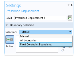
In the Settings window that opens, select an option from the Selection list, for example, Manual or All boundaries.
3
Click the Create Selection button () and enter a Selection name in the Create Selection window, for example, Fixed Constraint Boundaries. Click OK or press enter.
4
In the Model Builder the new Explicit node (now named Fixed Constraint boundaries) is added under Definitions. After creating these named selections, the Selection list displays the name in the list as in Figure 6-18.
Figure 6-17: Creating a selection from the Settings window for a Fixed Constraint node.
Figure 6-18: After creating these named selections, the Selection list displays the new name in the list, making it simple to choose it when adding additional boundary conditions such as a Prescribed Displacement node.
Create an Explicit Selection from the Selection List Window
Continue using the same model for this example, which demonstrates how to identify specific boundaries to add to a new Explicit selection:
1
In the Model Builder, click the Component 1 node.
2
Open The Selection List Window. Right-click and select Float to detach the window from the COMSOL Desktop.
The COMSOL Multiphysics software displays the geometric entities in the Selection List based on where in the model you are working. Other nodes can be clicked to display the list of geometric entities. For example, the Materials, Solid Mechanics (in this example), Mesh, and Geometry nodes. Experiment in the COMSOL Desktop by clicking on different nodes and observing the changes in the Selection List and Graphics windows.
3
In the Graphics window toolbar, click the Select Boundaries button (). The Selection List displays a list of all boundaries in the geometry. Click the Select Domains, Select Edges, or Select Points buttons in the Graphics window and observe how the list and the geometry changes based on the geometric entity level.
4
In the Selection List window, click to pick the boundaries you want to add to an Explicit selection:
-
-
-
To help you identify the boundary, the boundaries that you picked are highlighted in red in the Graphics window.
5
Once the boundaries are chosen, click the Create Selection button () and enter a Selection name in the Create Selection window, for example, Tube boundaries. Click OK or press enter.
6
Go to the Model Builder. The new Explicit node (now named Tube boundaries) is added under Definitions.
Hiding the Selected Geometric Entities
To hide the selected geometric entities in the named selection nodes, right-click the node and choose Hide Selection (). To show the hidden selection again, right-click the node and select Show Selection ().