|
|
Isolated vertices are automatically meshed if a Free Tetrahedral, Free Triangular, Free Quad, or Edge operation is built with Geometric entity level set to Remaining or Entire Geometry. For the Mapped operation, isolated vertices are automatically meshed if Geometric entity level is set to Remaining.
|
|
•
|
|
•
|
In The Mesh Toolbar, choose Vertex from the More Generators (
|
|
•
|
|
•
|
Choose Entire geometry to generate a vertex mesh for the entire geometry.
|
|
•
|
Choose Remaining to specify a vertex mesh for the remaining, unmeshed vertices.
|
|
•
|
Choose Point (3D and 2D) or Boundary (1D) to specify the points for which you want to create a mesh. Choose Manual in the Selection list to select the points in the Graphics window, choose a named selection to refer to a previously defined selection, or choose All points (3D and 2D) or All boundaries (1D) to select all points.
|
|
|
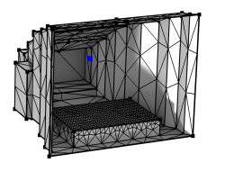
For a tutorial using the Vertex operation, see
Small Concert Hall Acoustics: Application Library path Acoustics_Module/Building_and_Room_Acoustics/small_concert_hall.
|
|
|