Use Mapped (

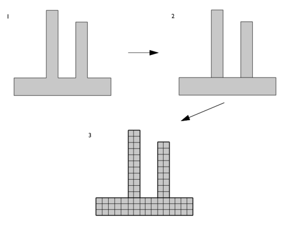
) to generate a structured quadrilateral mesh on boundaries in 3D and domains in 2D, as shown in
Figure 8-85. The operation can also be used to remesh imported meshes in 3D.
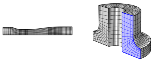
For imported meshes in 3D, use Mapped to remesh one or several faces. The operation separates the selected boundaries from the mesh, creates geometry from the separated mesh, meshes the geometry, and then copies the new generated mesh onto the original mesh. Edges adjacent to faces outside the selection are kept unchanged, while other edges are remeshed.
To add a Mapped (

) node, select boundaries (3D) or domains (2D) in the
Graphics window, then choose one of the following:
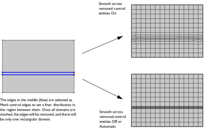
Use the Smooth across removed control entities setting to smooth the transition in element size across removed control entities. Use
Automatic (default) to let the algorithm decide if to apply smoothing or not. Smoothing will be applied if, for example, 2D domains adjacent to removed edges contain triangular elements only. When set to
On, the mesher adjusts the sizes of the mesh elements to get a smoother transition from large to small elements by adjusting the locations of the mesh vertices on the entity that is removed. Select
Off to not adjust the mesh. When set to
On, you can specify the number of smoothing iterations in the
Number of iterations field. In the
Maximum element depth to process field you can specify the maximum element depth for the mesh vertices to be smoothed.
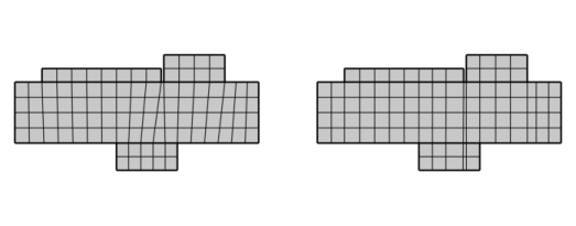
Select the Adjust edge mesh checkbox (cleared by default) to allow the mapped mesher to adjust the mesh on edges that are not already meshed and where no explicit distribution is applied in order to reduce the element skewness (see
Figure 8-88 below).
In this section you can choose between two different interpolation methods in the Interpolation method list. This specifies how the mapped meshing operation determines the positions of the interior mesh vertices. Select
Automatic (default) to let the mapped meshing operation determine a suitable interpolation method automatically. In many cases, the interpolation methods give the same result. If you select
Transfinite in 2D, the positions of the interior mesh vertices are determined by transfinite interpolation in the 2D parameter space of the corresponding surface. This method works best for faces with smooth surface parameterization. If you select
Transfinite in 3D, transfinite interpolation is done in 3D to determine these positions. This method works best if the shape of the exterior edges represent the shape of the surface in a good way.