Free Triangular
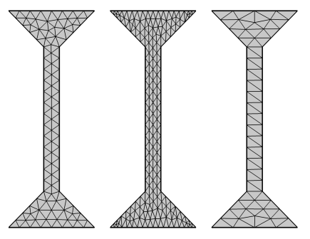
Use Free Triangular () to create an unstructured triangular mesh on boundaries in 3D and domains in 2D, as shown in Figure 8-64. The Free Triangular operation can also be used to remesh faces of imported surface meshes in 3D.
Figure 8-64: Use Free Triangular to create unstructured triangle meshes on faces in 3D (left) and on domains in 2D (right).
You can control the number, size, distribution, and refinement of elements by using Size, Size Expression, Distribution, and Corner Refinement subnodes (only Size and Distribution subnodes are available for Finalizing the Mesh).
For imported meshes in 3D, use Free Triangular to remesh one or several faces. The operation separates the selected boundaries from the mesh, creates geometry from the separated mesh, meshes the geometry, and then copies the new generated mesh onto the original mesh. Edges adjacent to faces outside the selection are kept unchanged, while other edges are remeshed.
Only surface meshes with first-order elements can be remeshed. Clear the Import domain elements checkbox in the mesh Import node to import only boundary elements. Select checkbox Import as linear elements to ignore second-order mesh data. See Importing Meshes for more information.
To add a Free Triangular node, select one or several boundaries (3D) or domains (2D) in the Graphics, then choose one of the following:
Right-click in the Graphics window and select Free Triangular () from The Graphics Context Menu.
In The Mesh Toolbar, choose Free Triangular from the More Generators () menu (3D components and parts) or click the Free Triangular () button (2D).
Right-click a Mesh node and choose Free Triangular (). For 3D components and parts, this is selected from the More Generators menu.
Then enter the properties for the triangular meshing operation using the following sections:
Entity Selection
Define the boundaries (3D) or domains (2D) where you want to create an unstructured triangular mesh. Choose the level of the geometry from the Geometric entity level list:
Choose Remaining to specify unstructured triangular mesh for remaining, unmeshed domains.
Choose Entire geometry to create an unstructured triangular mesh in the entire geometry.
In 2D and 2D Axial symmetry, for the options Entire geometry and Remaining, the operation will mesh all remaining entities, even those that are not adjacent to a domain.
Choose Boundary (3D) or Domain (2D) to specify the geometric entities for which you want to create an unstructured triangular mesh. Choose Manual in the Selection list to select the boundaries or domains in the Graphics window, choose a named selection to refer to a previously defined selection, or choose All boundaries (3D) or All domains (2D) to select all entities.
For imported meshes in 3D, the available options in the Geometry entity level list are Manual and All boundaries.
Scale Geometry
To scale the geometry during the meshing operation, change the x-scale, y-scale, and z-scale in 3D to positive real numbers, as shown in Figure 8-65. If any of the scale factors are not equal to one (1), the software scales the geometry in those directions before meshing. After meshing, it restores the geometry and mesh to fit the original size.
The scale factors make it possible to generate meshes that are anisotropic, and is one alternative to use if the mesh generator creates many elements due to a thin geometry or large aspect ratios in the geometry (compare the first and last mesh in Figure 8-65). Compare this to changing the Resolution of narrow region parameter in a mesh Size attribute to only affect the mesh size in narrow regions. In 3D, consider using the Collapse Face Regions or Remove Details to remove narrow regions, if these are not important to the computation at hand.
Figure 8-65: Three hourglass shaped geometries meshed with triangular meshes where the mesh in the narrow region can be more or less resolved by scaling the geometry in the background. The first geometry (left) is not scaled. The geometry in the middle is scaled with a factor 2 in the x direction. The last geometry (right) is scaled with a factor 0.5 in the x direction before meshing it and restoring it to its original size. Note that the scaling influences the whole domain, not only the narrow region in the middle.
Narrow Domain Regions
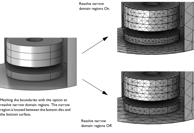
Select the checkbox Resolve narrow domain regions to allow the element size to be smaller close to narrow domain regions, as shown in Figure 8-66. The surface mesh will be the same as if the Free Tetrahedral operation had been built in the adjacent domain. Clear the checkbox to generate a triangular mesh without accounting for narrow domain regions. The checkbox is selected by default for imported meshes and is cleared by default for meshes that are operating on geometry.
Figure 8-66: Meshing the boundaries using the option Resolve narrow domain regions. Turning on the option resolves the surface mesh as if a tetrahedral mesh was created in the narrow region (upper right).
Control Entities
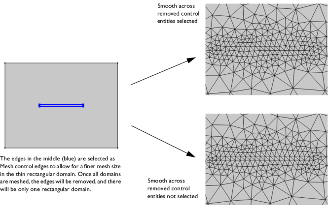
Use the Smooth across removed control entities setting to smooth the transition in element size across removed control entities. Use Automatic (default) to let the algorithm decide if to apply smoothing or not. Smoothing will be applied if, for example, 2D domains adjacent to removed edges contain triangular elements only. When set to On, the mesher adjusts the sizes of the mesh elements to get a smoother transition from large to small elements by adjusting the locations of the mesh vertices on the entity that is removed. Select Off to not adjust the mesh. When set to On, you can specify the number of smoothing iterations in the Number of iterations field. In the Maximum element depth to process field you can specify the maximum element depth for the mesh vertices to be smoothed.
Figure 8-67: Comparing meshes where Smooth across removed control entities has been used vs. not used. With the Smooth across removed control entities set to On, the sizes of the triangle elements are adjusted (upper-right image) and with the option set to Off, the triangle mesh is not adjusted (lower-right image). As the domains are meshed with a triangle mesh, the Automatic option gives the same result as On.
Mesh Generation
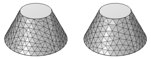
Here you can specify the triangulation method used when creating the triangular mesh. Select Automatic (default) to let the software use the method that is best suited for the geometry. Select Delaunay to use a method based on a Delaunay algorithm. This results in a mesh with more irregular structure. Select Advancing front to use a method based on an advancing front algorithm. This results in a mesh with more regular structure.
Figure 8-68: A cone meshed with a triangular mesh using different triangulation methods. The image to the left shows a mesh generated using the Delaunay method. The image to the right shows a mesh generated with the Advancing front.
Mesh Preprocessing
You can optionally simplify the mesh when remeshing faces in an imported mesh. The simplification can remove small defects typically present in mesh data from measurements, such as tomography, and it can speed up the process by removing unnecessary elements. The Simplify mesh checkbox is selected by default to enable simplification.
The Relative simplification tolerance (default value: 0.01) is relative to the dimensions of the entire geometry and specifies a global limit for how much the mesh can be modified. The Defect removal factor (default value: 1) is relative to the local feature size, as estimated by the algorithm, and is combined with the global limit to produce a limit for how much the mesh can be modified at a certain location. If the mesh contains many defects that you want to remove, you could try to increase the value of the Defect removal factor. If the mesh describes the desired geometry with high accuracy, you might want to decrease this factor instead.
Information
For information, see Generated and Modified Elements.
For a tutorial about adjusting the mesh size, see
Adjusting the Element Size for the Unstructured Mesh Generator:
Application Library path COMSOL_Multiphysics/Meshing_Tutorials/piston_mesh
For a tutorial showing a swept triangular mesh, see
Steam Reformer: Application Library path Chemical_Reaction_Engineering_Module/Reactors_with_Porous_Catalysts/steam_reformer
For a tutorial showing the operation used in 3D, see
Forced Convection Cooling of an Enclosure with Fan and Grille: Application Library path Heat_Transfer_Module/Power_Electronics_and_Electronic_Cooling/electronic_enclosure_cooling
For a tutorial showing the operation used in 2D, see Stresses in a Pulley:
Application Library path COMSOL_Multiphysics/Structural_Mechanics/stresses_in_pulley