The operations provide information about the elements the operation generated. This information is found under the Information Section of the operation. The software provides automatic detection of details and regions that might cause problems. Depending on the severity of the problem, the meshing operations display the information in
Information Nodes,
Warning Nodes, or
Error Nodes.
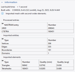
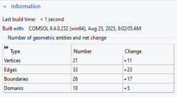
After building a meshing sequence or an operation that generates mesh, a table appears showing the generated elements, as shown in Figure 8-19. It displays the type of elements, how many elements were generated of each type, how many elements that were modified (if any), and the minimum and average quality for each element type. The quality measure presented is the skewness of the elements. To evaluate quality with other measures, use
Mesh Statistics.

Information nodes (

) appear when a mesh can be built but the meshing algorithms determine that there is something that might deserve your attention. This can be very small geometry details (small faces, short edges, and so on) or that mesh elements of low quality appeared. Check the information message and any selection of entities to determine if something needs to be modified and how. Low quality elements can lead to difficulties for the solver to converge or make the solution sensitive to small changes in the mesh.
For elements of low quality, it is useful to plot elements as described in Displaying Mesh Element Quality and the Mesh Element Size. Use the information about the minimum element quality in the
Information node to set an appropriate value for the Element Filter expression.
Information,
Warning and
Error nodes can contains details with coordinates for the location of the problem, indicated by red points in the
Graphics window. Select a location from the list and click the
Center at Coordinates button to automatically center the camera and zoom in on the problematic area. For 3D meshes, click the
Clip Around Coordinates button to add a
Clip Sphere around the coordinates. This makes it easier to investigate the problematic area, especially if it is located inside a complex geometry. Click the
Remove Clipping button in the Settings window to remove the Clip Sphere.
Warning nodes (

) appear when a mesh can be built but might need some extra tuning to be suitable for computations. Check the warning message and any selection of entities. There is often more than one level of warnings providing details of the cause, so check all subnodes if any. It is possible to continue the computation with warning nodes in the meshing sequence and you might still get a valid result. However, if you get problems in the computation or obtain unexpected results, the warnings might indicate the cause. Warning nodes can also appear elsewhere in the model tree (for example, for an operator that requires some argument that is missing).
If the mesh generation cannot continue, all building stops. The operation gets Warning status if some entities could be meshed, indicated by an orange triangle in the lower-right corner of the operation’s icon (see Dynamic Nodes in the Model Builder). If nothing could be built, the operation gets Error status, which the program indicates by adding a red cross in the lower-right corner of the operation’s icon. If the operation is part of a sequence build, the build stops and the preceding node becomes the current node.