Use the Merge Entities (

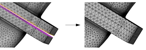
) operation to merge entities of a 3D mesh, as shown in
Figure 8-58. It is possible to merge boundaries, edges, and points by specifying entities to keep and the entities to remove. Depending on the specified tolerance, only parts of the entities are merged, similar to the geometry operation
Collapse Face Regions.
Enter the properties for the Merge Entities node using the following sections:
Use the option Pairing of entities to keep and remove to choose how to pair the entities to merge. Select
Automatic (default) to enter all entities in the
Geometric Entity Selection and let the operation choose which entities to keep and which entities to remove. Select
Manual to enter the entities to keep and remove in the
Entities to Keep and
Entities to Remove, respectively.
Click the Active button to toggle between turning ON

and OFF

selections. Select all the entities to merge, for example by clicking in the
Graphics window.
Click the Active button to toggle between turning ON

and OFF

selections. Select the entities to keep, for example by clicking in the
Graphics window.
Click the Swap Entities to Keep and Remove button (

) to swap the entities in the selection to keep above and the entities in the selection to remove below.
Click the Active button to toggle between turning ON

and OFF

selections. Select the entities to remove, for example by clicking in the
Graphics window.
Use the Maximum distance setting to control the maximum distance to bridge when merging entities of the mesh, as shown in
Figure 8-59.
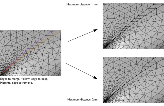
Choose Relative to enter a value in the
Relative distance field. This value is relative to the length of the longest side of the mesh’s bounding box. Select
Absolute to specify a value in the
Absolute distance field. When the operation is built with the setting
Automatic (the default), the value in the
Absolute distance field is automatically updated to correspond to the actually used distance. The automatic tolerance is based on the size of the bounding box of the mesh.
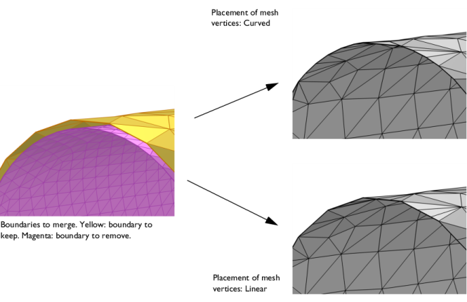
Use the Placement of mesh vertices setting to specify if the mesh vertices of the entities to be removed will be placed on the
Curved (default) or
Linear representation of the entities to keep, as shown in
Figure 8-60.
Use the Deformation propagation edit field (or slider) to determine how much of the deformation on the remove side is propagated further into the side to remove. A low value will only move the mesh vertices closest to the entity to remove while a high value will shift the whole connected component toward the keep side.
Use the Method setting to specify the way to match a determined pair of entities to keep and remove. The method
Make imprints means that the keep entities make an imprint on the remove entities and, symmetrically, the remove entities make an imprint on the keep entities. Then, only the overlapping imprints are merged.
Use the Precision edit field or slider to specify the accuracy of the imprint. A low precision will give a sloppier matching, meaning that regions of entities with approximately the same shape will be matched without imprinting, while high precision gives a more accurate imprint but also means that small entities and details can appear.
The method One-to-one forces the entities on the remove side to be matched with the keep side without any imprints. This is useful when the shape is approximately the same and you want to match them exactly. Note that if the entities have too different shape, the merge will generally not be successful with this option.