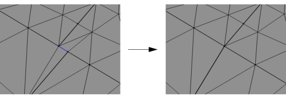
Use the Collapse Entities (

) operation to collapse boundaries or edges of a 3D mesh, as shown in
Figure 8-30 and
Figure 8-31. A domain without mesh can be collapsed if all surrounding surfaces are collapsed.

Enter the properties for the Collapse Entities node using the following sections:
Select the geometric entity level from the Geometric entity level list. The possible choices are
Entire geometry (the default),
Boundary, or
Edge. For
Entire geometry, the selection below is not available.
Click the Active button to toggle between turning ON

and OFF

selections. Select the edges or boundaries to collapse from in the
Graphics window.
Use the Maximum size setting to control the size of the edges or boundaries to collapse in the mesh. Choose
Relative to enter a value in the
Relative tolerance field. This value is relative to the length of the longest side of the mesh bounding box. Select
Absolute to specify a value in the
Absolute tolerance field. This value is determined by measuring the size of the bounding box as well as the smallest entities in the selection, with a maximum value set by the size of the bounding box. The maximum value is not taken into account if only one entity is selected. When the operation is built with either of the settings
Automatic (the default) or
Relative, the values in the
Absolute tolerance field is automatically updated to correspond to the actually used tolerance. The value is also shown in the
Information section.

