Edge
The operation meshes edges in 1D, 2D, and 3D. This is useful not only for intervals in 1D, but also for applications where the physics is solved on edges in 2D and 3D, as seen in Figure 8-41.
Figure 8-41: The image to the left shows the mesh for a pipe flow simulation on edges in 2D. The image to the right shows the edge mesh for beams (highlighted in blue) connected to solids.
You can control the number of elements and the distribution of elements in the edge mesh by using Size and Distribution nodes.
To create an edge mesh, select edges in the Graphics window, then:
Right-click in the Graphics window and select Edge () from The Graphics Context Menu.
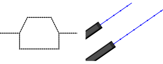
In the Mesh toolbar, choose Edge from the Boundary menu () (3D components) or click Edge () (2D or 1D components).
Right-click the Mesh node and choose Edge (under Boundary Generators in 3D).
Then enter the properties using the following sections:
Entity Selection
To define the edges where you want a create a mesh, first choose the level of the geometric entities from the Geometric entity level list:
Choose Entire geometry to specify an edge mesh for the entire geometry.
Choose Remaining to specify an edge mesh for remaining, unmeshed edges.
Choose Edge (3D), Boundary (2D), or Domain (1D) to specify the edges for which you want to create a mesh. Choose Manual in the Selection list to select the edges in the Graphics window, choose a named selection to refer to a previously defined selection, or choose All edges (3D), All boundaries (2D), or All domains (1D) to select all edges.
Control Entities
Select the Smooth across removed control entities check box to smooth the transition in element size across removed Controlling the Mesh Size Using Mesh Control Entities. You can specify the number of smoothing iterations in the Number of iterations field. In the Maximum element depth to process field you can specify the maximum element depth for the mesh points to be smoothed.
Figure 8-42: Comparing meshes where Smooth across removed control entities has been used vs. not used. The two vertices adjacent to the edge in the middle (highlighted in blue in left image) are designated as Mesh Control Vertices and a finer mesh size is set on the edge between them. When all parts of the edge have been meshed, the vertices are removed, leaving only one single edge. With the Smooth across removed control entities check box is selected, the sizes of the edge elements are adjusted to get a smoother transition from large to small mesh elements (upper right edge). Clear the check box to not adjust the mesh (lower right edge).
For a 3D tutorial, see Connecting Beams and Solids:
Application Library path Structural_Mechanics_Module/Beams_and_Shells/beam_solid_connection.
For a 3D tutorial, see Magnetic Field of a Helmholtz Coil:
Application Library path ACDC_Module/Devices,_Inductive/helmholtz_coil.
For a 2D tutorial, see Slurry Transport:
Application Library path Pipe_Flow_Module/Tutorials/slurry_transport.
For a 1D tutorial, see Lithium-Sulfur Battery:
Application Library path Battery_Design_Module/Batteries,_General/lithium_sulfur.