You are viewing the documentation for an older COMSOL version. The latest version is
available here.
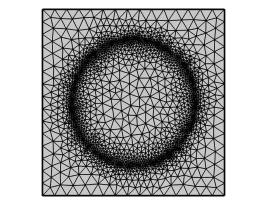
Use a Size Expression node (

) to specify the size of mesh elements as an expression evaluated on a grid (as shown in
Figure 8-67), a computed solution, or a temporary solution corresponding to the initial value of a study step.
It is possible to add a Size Expression node both as a global node and as a local node. Free triangular, tetrahedral, and quadrilateral mesh operations that follow below the
Size Expression node in the meshing sequence take the size expression into account.
For some types of adaptation and error estimation in the study settings (using mesh initialization), the adaptive solver add a Size Expression node to the meshing sequences that represent the adaptive mesh generation, but you can also add a
Size Expression node to set up a mesh size expression of your choice. Right-click a
Mesh node to add a
Size Expression node from the context menu.
|
|
Only one Size Expression node per meshing sequence is supported.
|
To add this node as a global node, right-click a Mesh node and select
Size Expression. To add this as a subnode, right-click a mesh
Generators node and select
Size Expression. Also see
Global vs. Local Attributes.
To add Size as a global node:
|
•
|
In the Mesh toolbar, click Sizing (  ) and select Size Expression (  ).
|
To add Size Expression as a local attribute, right-click a mesh
Generators node and select
Size Expression. Also, see
Global vs. Local Attributes.
|
•
|
Choose Entire geometry to specify the size expression for the entire geometry.
|
|
•
|
Choose Domain, Boundary, Edge (3D), or Point (2D and 3D) to specify the domains, boundaries, edges, or points for which you want to refine the mesh. Choose Manual from the Selection list to select the domains, boundaries, edges, or points in the Graphics window, choose a named selection to refer to a previously defined selection, or choose All domains, All boundaries, All edges, or All Points to select all domains, all boundaries, all edges, or all points, respectively.
|
From the Evaluate on list, choose
Grid (the default),
Solution, or
Initial expression to specify whether the evaluation is done on a grid, a solution, or an expression evaluated using initial values.
Use the Size expression field to enter an expression for the absolute element size as a function of
x,
y, and
z (depending on the space dimension). You can also use parameters and global functions, variables, and materials in the expression, but no features from the component are available. The actual size used in a coordinate is the minimum of the specified size expression and the result of the other size parameters (such as the maximum element size and the curvature factor), but this minimum is cut off by the specified minimum element size on a given entity, which acts as a lower bound. If the expression evaluates to something smaller than the minimum element size, you get a warning that the value was cut off.
|
|
The Size expression field uses the unit system defined by the component. The evaluated value of the expression is interpreted as a length in the geometry’s unit system.
|
To control the grid, you can specify the Grid type, which can be
Resolution, where you specify the number of isotropic cells per dimension in the grid in the
Number of cells per dimension field, or
Cell size, where you specify the side length of a grid cell in the
Side length field.
From the Solution list, select the solution to use for evaluation.
From the Solution selection list, select which solution that should be used to evaluate error estimates:
|
•
|
Select Use last to use the last solution.
|
|
•
|
Select Use first to use the first solution.
|
|
•
|
Select All (the default for Eigenvalue studies) to use all solutions from that study.
|
|
•
|
Select Manual to use a specific solution number that you specify as solution indices in the Index field.
|
In the Weights field (only available when
Solution selection is
Manual or
All), enter weights as a space-separated list of positive (relative) weights so that the error estimate is a weighted sum of the error estimates for the various solutions (eigenmodes). The default value is 1, which means that all the weight is put on the first solution (eigenmode). That is, any omitted weight components are treated as zero weight.
From the Type of expression list, choose
Error indicator (the default) or
Absolute size.
If you select Error indicator, the following settings appear:
The Error expression list, where you can add expressions for the error, for example, in terms of the dependent variables (including the variables for error estimation). You can use any expression, including field variables and their derivatives, defined in the domain. Use the
Active column to control which error expressions that are active by selecting or clearing the corresponding check box.
The Error order column is available when
Element selection is set to
Rough global minimum and forms an array of
h-exponents for the decrease of the error expression. This array has the same indexing as the error expression’s indexing (for an error expression with two expressions such as
errexpr1,
errexpr2 and error orders = 2, 3, it means that
errexpr1 =
O(
h2) and
errexpr2 =
O(
h3)). When the adaptation method is used, these numbers are filled in automatically based on the
Residual order and
Error estimate settings (on the adaptation study). The shape functions can also influence this order. Note that these order numbers need to be positive to generate additional elements (element growth).
Use the Move Up (

),
Move Down (

),
Add (

)and
Delete (

) buttons as needed. If you use several expressions, such as one for each solution component, the error expressions are added to form the sum of all of them. Or right-click a table cell and select
Move Up,
Move Down,
Add, or
Delete.
In 2D, use the Refinement method list to control how to refine mesh elements. Select:
|
•
|
Longest to make the solver refine only the longest edge of an element.
|
|
•
|
Regular to make the solver refine elements in a regular pattern.
|
Use the Element selection list to specify how the element refinement vector is determined from the error expression. Select:
|
•
|
Rough global minimum to minimize the L2 norm of the error by refining a fraction of the elements with the largest error in such a way that the total number of elements increases roughly by a factor greater than 1 specified in the accompanying Element growth rate field. The default value is 1.7, which means that the number of elements increases by roughly 70%.
|
|
•
|
Fraction of worst error to refine elements whose local error indicator is larger than a given fraction of the largest local error indicator. Use the accompanying Element fraction field to specify the fraction. The default value is 0.5, which means that the fraction contains the elements with more than 50% of the largest local error.
|
|
•
|
Fraction of elements to refine a given fraction of the elements. Use the accompanying Element fraction field to specify the fraction. The default value is 0.5, which means that the solver refines about 50% of the elements with the largest local error indicator.
|
If you select Absolute size, the following setting appears:
In the Size expression field, type an expression for the element size (in terms of variables defined by the solution).
|
|
The Size expression field uses the unit system defined by the component. The evaluated value of the expression is interpreted as a length in the geometry’s unit system.
|
From the Mesh list, select a mesh (on the same geometry as the
Size Expression node) on which the interpolation should be done. If
Automatic (the default) is chosen, a mesh will be created automatically.
From the Study step list, choose a study step (for which
Get Initial Value for Step will be run). If you choose
None (the default), an empty study is created. The mesh that was specified above is used in the referenced or empty study step that you choose. These actions take place in a copy of the model and are therefore not visible in the
Model Builder tree.
Use the Size expression field to enter an expression for the absolute element size as a function of
x,
y, and
z (depending on the space dimension). You can also use variables and materials from the physics, parameters, and global functions and materials in the expression. The actual size used in a coordinate is the minimum of the specified size expression and the result of the other size parameters (such as the maximum element size and the curvature factor), but this minimum is cut off by the specified minimum element size on a given entity, which acts as a lower bound. If the expression evaluates to something smaller than the minimum element size, you get a warning that the value was cut off.
|
|
The Size expression field uses the unit system defined by the component. The evaluated value of the expression is interpreted as a length in the geometry’s unit system.
|
The selection in the Update when parameter is changed list provides the possibility to have the cache cleared whenever the values of the selected parameter are changed.
In this section, you can control the amount of smoothing of the mesh size expression. The Maximum size field growth rate (default: 1.4) controls how fast the size field can grow. It is a factor that must be larger than 1.0. Use a higher value to make the mesh coarser closer to areas with a small mesh size, which results in fewer mesh elements.