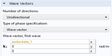
Electromagnetic Waves, Beam Envelopes
For many simulation problems you have some boundaries between different materials that create reflected waves propagating in the backward direction. Thus, the default setting for the Electromagnetic Waves, Beam Envelopes interface is to do bidirectional simulations.
However, for the directional coupler problem, we do not expect any reflected waves. So it is best to select unidirectional propagation in this case.
As will be demonstrated in the second part of this tutorial, the bidirectional formulation can also be used for solving for two modes propagating in the same direction. This configuration will further reduce the requirement on the mesh size.
Since both unidirectional and bidirectional studies will be performed, we will create different physics interfaces, mesh nodes and study nodes for the different studies.
1
2
3
4
Enter ewbe.beta_1 in the x text field of the k1 table, as shown in the figure.
This sets the wave vector to be that of the lowest waveguide mode. With this wave vector setting, the phase factor of the electric field perfectly matches the lowest mode, but it is slightly mismatched to the also excited higher-order mode, as discussed in the Model Definition section.
The expression ewbe.beta_1 is colored orange, as a warning that this variable has not yet been defined. We will define it, when adding the first port below.
Port 1
To excite the wave at the input boundary and to absorb the wave at the output boundary, two numeric ports per boundary are used. The first two ports excite the waveguides.
Each numeric port has a Boundary Mode Analysis study step associated with it. The Boundary Mode Analysis study performs an Eigenvalue study to find the mode fields and the propagation constant associated to the port. The Boundary Mode Analysis steps will be defined first for Port 1 in section Study 1 and later for the remaining ports in section Study, Unidirectional.
1
2
3
Since this is the first added Port, the Wave excitation at this port list is automatically set to On.
Now duplicate the first port.
Port 2
1
Next, create the absorbing ports at the other end of the waveguide structure.
Port 3
1
2
3
Duplicate this port.
Port 4
1