PDF

Anode Film Resistance Effect on Cathodic Corrosion Protection
Introduction
This example is an extension of the Corrosion Protection of an Oil Platform Using Sacrificial Anodes model. The model exemplifies how the steel corrosion rate increases over time due to build-up of a resistive film on the sacrificial anodes, formed by reaction products.
Model Definition
The zinc dissolved on a sacrificial anode may react further to form various compounds. One example is Zn(OH)2 formation according to
(1)
In marine saline environments, however, other products may also be formed, for instance chloride and hydroxychloride compounds. This is not included in the model.
In this example we assume that 1% of the zinc ions dissolved precipitate as a dense film on the zinc anode surface, resulting in a growing film resistance over time.
Constant molar mass, density and conductivity are assumed for the species forming the resistive film. In reality, these properties may change over time due to a changing porosity of the depositing film.
The model also includes secondary current distribution electrode kinetics on the protected steel structure, defining simultaneous metal dissolution and oxygen reduction (mixed potential), in analogy with for instance the Galvanized Nail and the Cathodic Protection of Steel in Reinforced Concrete examples.
The model is solved in a one year time-dependent simulation. The symmetry of the model geometry has been considered in order to reduce the problem size, as shown in Figure 1.
Figure 1: Model geometry. Symmetry was considered to reduce the model size.
Results and Discussion
Figure 2 and Figure 3 show the electrode potential vs SHE at the start of the simulation and after one year, respectively. The potential on the steel structure is higher at the end of the simulation, resulting in a reduced corrosion protection.
Figure 2: Potential vs SHE at t=0.
Figure 3: Potential vs SHE at t=365 days.
Figure 4 shows the resulting anode film thickness after one year. The film thickness is fairly uniform.
Figure 4: Precipitated anode film thickness at t=365 days.
Figure 5 shows the steel corrosion current density for two points: one at the upper part of one of the legs, and one at the inner bottom part of one of the legs. As can be seen the corrosion rates increase significantly over time and approach the limiting current density for oxygen (0.1 A/m2) used in the model.
Figure 5: Corrosion current density vs time.
Notes About the COMSOL Implementation
An Electrode Surface boundary node is used for the zinc anodes in order to define the surface concentration of precipitated products, the film resistance potential drop, and the zinc oxidation reaction.
Application Library path: Corrosion_Module/Cathodic_Protection/anode_film_resistance
Modeling Instructions
From the File menu, choose New.
New
In the New window, click  Model Wizard.
Model Wizard
1
In the Model Wizard window, click  3D.
2
In the Select Physics tree, select Electrochemistry>Primary and Secondary Current Distribution>Secondary Current Distribution (cd).
3
Click Add.
4
Click  Study.
5
In the Select Study tree, select Preset Studies for Selected Physics Interfaces>Time Dependent with Initialization.
6
Global Definitions
Parameters 1
1
In the Model Builder window, under Global Definitions click Parameters 1.
2
In the Settings window for Parameters, locate the Parameters section.
3
Click  Load from File.
4
Geometry 1
The model geometry is available as a parameterized geometry sequence in a separate MPH-file. If you want to build it from scratch, follow the instructions in the section Appendix — Geometry Modeling Instructions. Otherwise load it from file with the following steps.
1
In the Model Builder window, expand the Component 1 (comp1)>Geometry 1 node.
2
Right-click Geometry 1 and choose Insert Sequence.
3
4
In the Geometry toolbar, click  Build All.
5
Click the  Zoom Extents button in the Graphics toolbar.
6
Click the  Transparency button in the Graphics toolbar.
Secondary Current Distribution (cd)
Electrolyte 1
1
In the Model Builder window, under Component 1 (comp1)>Secondary Current Distribution (cd) click Electrolyte 1.
2
In the Settings window for Electrolyte, locate the Electrolyte section.
3
From the σl list, choose User defined. In the associated text field, type sigma_sea.
Electrode Surface 1 - Zinc
1
In the Physics toolbar, click  Boundaries and choose Electrode Surface.
2
In the Settings window for Electrode Surface, type Electrode Surface 1 - Zinc in the Label text field.
3
Locate the Boundary Selection section. From the Selection list, choose Zinc.
4
Click to expand the Dissolving-Depositing Species section. Click  Add.
5
6
Click to expand the Film Resistance section. From the Film resistance list, choose Thickness and conductivity.
7
From the Δs list, choose Total electrode thickness change (cd/es1).
8
In the σfilm text field, type sigma_ZnOH2.
Zn Oxidation
1
In the Model Builder window, expand the Electrode Surface 1 - Zinc node, then click Electrode Reaction 1.
2
In the Settings window for Electrode Reaction, type Zn Oxidation in the Label text field.
3
Locate the Stoichiometric Coefficients section. In the n text field, type 2.
4
In the Stoichiometric coefficients for dissolving-depositing species: table, enter the following settings:
5
Locate the Equilibrium Potential section. In the Eeq text field, type Eeq_Zn.
6
Locate the Electrode Kinetics section. From the Kinetics expression type list, choose Anodic Tafel equation.
7
In the i0 text field, type i0_Zn.
8
In the Aa text field, type A_Zn.
Electrode Surface 2 - Steel
1
In the Physics toolbar, click  Boundaries and choose Electrode Surface.
2
In the Settings window for Electrode Surface, type Electrode Surface 2 - Steel in the Label text field.
3
Locate the Boundary Selection section. From the Selection list, choose Steel.
Steel Oxidation
1
In the Model Builder window, expand the Electrode Surface 2 - Steel node, then click Electrode Reaction 1.
2
In the Settings window for Electrode Reaction, type Steel Oxidation in the Label text field.
3
Locate the Equilibrium Potential section. In the Eeq text field, type Eeq_Fe.
4
Locate the Electrode Kinetics section. From the Kinetics expression type list, choose Anodic Tafel equation.
5
In the i0 text field, type i0_Fe.
6
In the Aa text field, type A_Fe.
Electrode Surface 2 - Steel
In the Model Builder window, click Electrode Surface 2 - Steel.
Oxygen reduction
1
In the Physics toolbar, click  Attributes and choose Electrode Reaction.
2
In the Settings window for Electrode Reaction, type Oxygen reduction in the Label text field.
3
Locate the Equilibrium Potential section. In the Eeq text field, type Eeq_O2.
4
Locate the Electrode Kinetics section. From the Kinetics expression type list, choose Cathodic Tafel equation.
5
In the i0 text field, type i0_O2.
6
In the Ac text field, type A_O2.
7
Select the Limiting current density check box.
8
In the ilim text field, type ilim_O2.
Initial Values 1
1
In the Model Builder window, click Initial Values 1.
2
In the Settings window for Initial Values, locate the Initial Values section.
3
In the phil text field, type -Eeq_Zn.
Symmetry 1
We can now define the symmetry along the planes in the geometry using the Symmetry node.
1
In the Physics toolbar, click  Boundaries and choose Symmetry.
2
Global Definitions
Default Model Inputs
Set up the temperature value used in the model.
1
In the Model Builder window, under Global Definitions click Default Model Inputs.
2
In the Settings window for Default Model Inputs, locate the Browse Model Inputs section.
3
In the tree, select General>Temperature (K) - minput.T.
4
Find the Expression for remaining selection subsection. In the Temperature text field, type T.
Mesh 1
1
In the Model Builder window, under Component 1 (comp1) click Mesh 1.
2
In the Settings window for Mesh, locate the Mesh Settings section.
3
From the Sequence type list, choose User-controlled mesh.
Size
1
In the Model Builder window, under Component 1 (comp1)>Mesh 1 click Size.
2
In the Settings window for Size, locate the Element Size section.
3
Click the Custom button.
4
Locate the Element Size Parameters section. In the Maximum element size text field, type 12.
5
In the Minimum element size text field, type 0.35.
6
In the Maximum element growth rate text field, type 1.6.
Free Triangular 1
1
In the Mesh toolbar, click  Boundary and choose Free Triangular.
2
Right-click Free Triangular 1 and choose Move Up.
3
In the Settings window for Free Triangular, locate the Boundary Selection section.
4
Click  Paste Selection.
5
In the Paste Selection dialog box, type 14 17 18 116 117 154 155 in the Selection text field.
6
Size 1
1
Right-click Free Triangular 1 and choose Size.
2
In the Settings window for Size, locate the Element Size section.
3
From the Predefined list, choose Fine.
Free Tetrahedral 1
1
In the Model Builder window, click Free Tetrahedral 1.
2
In the Settings window for Free Tetrahedral, click  Build All.
Study 1
Step 1: Current Distribution Initialization
1
In the Model Builder window, under Study 1 click Step 1: Current Distribution Initialization.
2
In the Settings window for Current Distribution Initialization, locate the Study Settings section.
3
From the Current distribution type list, choose Secondary.
Step 2: Time Dependent
1
In the Model Builder window, click Step 2: Time Dependent.
2
In the Settings window for Time Dependent, locate the Study Settings section.
3
From the Time unit list, choose d.
4
In the Output times text field, type 0 10 20 30 range(60,60,300) 365.
5
In the Home toolbar, click  Compute.
Results
Potential vs. SHE (V)
1
In the Model Builder window, under Results click Electrode Potential vs. Adjacent Reference (cd).
2
In the Settings window for 3D Plot Group, type Potential vs. SHE (V) in the Label text field.
3
Click to expand the Title section. From the Title type list, choose Manual.
4
In the Title text area, type Potential vs. SHE (V).
5
Locate the Plot Settings section. Clear the Plot dataset edges check box.
Streamline 1
1
In the Model Builder window, expand the Potential vs. SHE (V) node.
2
Right-click Streamline 1 and choose Disable.
Selection 1
1
In the Model Builder window, right-click Surface 1 and choose Selection.
2
In the Settings window for Selection, locate the Selection section.
3
From the Selection list, choose All Electrodes.
Potential vs. SHE (V)
1
In the Model Builder window, click Potential vs. SHE (V).
2
In the Potential vs. SHE (V) toolbar, click  Plot.
3
Click the  Zoom Extents button in the Graphics toolbar.
4
Click the  Transparency button in the Graphics toolbar.
5
In the Settings window for 3D Plot Group, locate the Data section.
6
From the Time (d) list, choose 0.
7
Click to expand the Title section. In the Parameter indicator text field, type Time= 0 d.
8
In the Potential vs. SHE (V) toolbar, click  Plot.
Oxide layer thickness
1
In the Model Builder window, under Results click Total Electrode Thickness Change (cd).
2
In the Settings window for 3D Plot Group, type Oxide layer thickness in the Label text field.
3
Locate the Plot Settings section. Clear the Plot dataset edges check box.
Selection 1
1
In the Model Builder window, expand the Oxide layer thickness node.
2
Right-click Surface 1 and choose Selection.
3
In the Settings window for Selection, locate the Selection section.
4
From the Selection list, choose Zinc.
5
In the Oxide layer thickness toolbar, click  Plot.
6
Click the  Zoom Extents button in the Graphics toolbar.
Local corrosion current density
1
In the Home toolbar, click  Add Plot Group and choose 1D Plot Group.
2
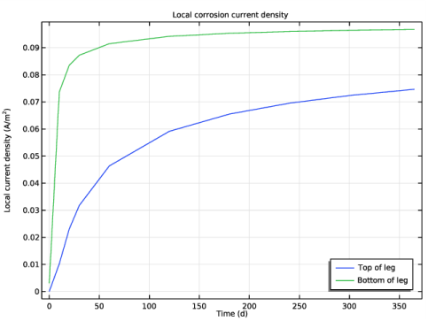
In the Settings window for 1D Plot Group, type Local corrosion current density in the Label text field.
3
Click to expand the Title section. From the Title type list, choose Label.
4
Locate the Legend section. From the Position list, choose Lower right.
Point Graph 1
1
Right-click Local corrosion current density and choose Point Graph.
2
Click the  Transparency button in the Graphics toolbar.
3
4
In the Settings window for Point Graph, click Replace Expression in the upper-right corner of the y-Axis Data section. From the menu, choose Component 1 (comp1)>Secondary Current Distribution>Electrode kinetics>cd.iloc_er1 - Local current density - A/m².
5
Click to expand the Legends section. Select the Show legends check box.
6
From the Legends list, choose Manual.
7
Point Graph 2
1
Right-click Point Graph 1 and choose Duplicate.
2
In the Settings window for Point Graph, locate the Selection section.
3
Select the  Activate Selection toggle button.
4
5
Locate the Legends section. In the table, enter the following settings:
6
In the Local corrosion current density toolbar, click  Plot.
Appendix — Geometry Modeling Instructions
From the File menu, choose New.
New
In the New window, click  Model Wizard.
Model Wizard
1
In the Model Wizard window, click  3D.
2
Geometry 1
Cylinder 1 (cyl1)
1
In the Geometry toolbar, click  Cylinder.
2
In the Settings window for Cylinder, locate the Size and Shape section.
3
In the Radius text field, type 3[m].
4
In the Height text field, type 0.5[m].
5
Locate the Position section. In the x text field, type -19[m].
6
Locate the Selections of Resulting Entities section. Find the Cumulative selection subsection. Click New.
7
In the New Cumulative Selection dialog box, type Steel in the Name text field.
8
You can collect geometry objects into cumulative selections that are available as input for subsequent geometry operations and when defining physics settings. The benefit of using selections here is a faster model set-up, since you can avoid selecting geometric objects from the graphics display.
9
In the Settings window for Cylinder, click  Build Selected.
10
Click the  Zoom Extents button in the Graphics toolbar.
Cylinder 2 (cyl2)
1
In the Geometry toolbar, click  Cylinder.
2
In the Settings window for Cylinder, locate the Size and Shape section.
3
In the Radius text field, type 1.5[m].
4
In the Height text field, type 20[m].
5
Locate the Position section. In the x text field, type -19[m].
6
In the z text field, type 0.5[m].
7
Locate the Selections of Resulting Entities section. Find the Cumulative selection subsection. From the Contribute to list, choose Steel.
Cone 1 (cone1)
1
In the Geometry toolbar, click  Cone.
2
In the Settings window for Cone, locate the Size and Shape section.
3
In the Bottom radius text field, type 1.5[m].
4
In the Height text field, type 1.6[m].
5
From the Specify top size using list, choose Angle.
6
In the Semiangle text field, type -30[deg].
7
Locate the Position section. In the x text field, type -19[m].
8
In the z text field, type 20.5[m].
9
Locate the Selections of Resulting Entities section. Find the Cumulative selection subsection. From the Contribute to list, choose Steel.
10
Click  Build Selected.
11
Click the  Zoom Extents button in the Graphics toolbar.
Cylinder 3 (cyl3)
1
In the Geometry toolbar, click  Cylinder.
2
In the Settings window for Cylinder, locate the Size and Shape section.
3
In the Radius text field, type 0.5[m].
4
In the Height text field, type 27[m].
5
Locate the Position section. In the x text field, type -19[m].
6
In the z text field, type 4.2[m].
7
Locate the Axis section. From the Axis type list, choose Cartesian.
Using this setting you can easily create a cylinder with an arbitrary axis orientation.
8
In the x text field, type 1.
9
In the y text field, type -1.
10
In the z text field, type 0.
11
Locate the Selections of Resulting Entities section. Find the Cumulative selection subsection. From the Contribute to list, choose Steel.
12
Click  Build Selected.
Cylinder 4 (cyl4)
1
In the Geometry toolbar, click  Cylinder.
2
In the Settings window for Cylinder, locate the Size and Shape section.
3
In the Radius text field, type 0.3[m].
4
In the Height text field, type 19[m].
5
Locate the Position section. In the x text field, type -9.5[m].
6
In the y text field, type -9.75[m].
7
In the z text field, type 4.2[m].
8
Locate the Axis section. From the Axis type list, choose x-axis.
9
Locate the Selections of Resulting Entities section. Find the Cumulative selection subsection. From the Contribute to list, choose Steel.
10
Click  Build Selected.
Cylinder 5 (cyl5)
1
In the Geometry toolbar, click  Cylinder.
2
In the Settings window for Cylinder, locate the Size and Shape section.
3
In the Radius text field, type 0.65[m].
4
In the Height text field, type 28[m].
5
Locate the Position section. In the x text field, type -20[m].
6
In the z text field, type 1[m].
7
Locate the Selections of Resulting Entities section. Select the Resulting objects selection check box.
8
From the Show in physics list, choose Off.
You can turn off the visibility of the selection outside the geometry sequence since it is not needed anywhere else.
Rotate 1 (rot1)
1
In the Geometry toolbar, click  Transforms and choose Rotate.
2
In the Settings window for Rotate, locate the Input section.
3
From the Input objects list, choose Cylinder 5.
4
Locate the Rotation section. From the Specify list, choose Euler angles (Z-X-Z).
With the option to define Euler angles you can easily set up a complex rotation in just one step.
5
In the α text field, type 60[deg].
6
In the β text field, type 30[deg].
7
Locate the Point on Axis of Rotation section. In the x text field, type -20[m].
8
Locate the Selections of Resulting Entities section. Find the Cumulative selection subsection. From the Contribute to list, choose Steel.
9
Click  Build Selected.
Mirror 1 (mir1)
1
In the Geometry toolbar, click  Transforms and choose Mirror.
2
In the Settings window for Mirror, locate the Input section.
3
From the Input objects list, choose Cylinder 5.
4
Select the Keep input objects check box.
5
Locate the Normal Vector to Plane of Reflection section. In the y text field, type 1.
6
In the z text field, type 0.
7
Locate the Selections of Resulting Entities section. Find the Cumulative selection subsection. From the Contribute to list, choose Steel.
8
Click  Build Selected.
Cylinder 6 (cyl6)
1
In the Geometry toolbar, click  Cylinder.
2
In the Settings window for Cylinder, locate the Size and Shape section.
3
In the Radius text field, type 0.3[m].
4
In the Height text field, type 10[m].
5
Locate the Position section. In the x text field, type -20[m].
6
In the z text field, type 10[m].
7
Locate the Selections of Resulting Entities section. Select the Resulting objects selection check box.
8
From the Show in physics list, choose Off.
Rotate 2 (rot2)
1
In the Geometry toolbar, click  Transforms and choose Rotate.
2
In the Settings window for Rotate, locate the Input section.
3
From the Input objects list, choose Cylinder 6.
4
Locate the Rotation section. From the Specify list, choose Euler angles (Z-X-Z).
5
In the α text field, type 60[deg].
6
In the β text field, type 60[deg].
7
Locate the Point on Axis of Rotation section. In the x text field, type -20[m].
8
In the z text field, type 10[m].
9
Locate the Selections of Resulting Entities section. Find the Cumulative selection subsection. From the Contribute to list, choose Steel.
10
Click  Build Selected.
Mirror 2 (mir2)
1
In the Geometry toolbar, click  Transforms and choose Mirror.
2
In the Settings window for Mirror, locate the Input section.
3
From the Input objects list, choose Cylinder 6.
4
Select the Keep input objects check box.
5
Locate the Normal Vector to Plane of Reflection section. In the y text field, type 1.
6
In the z text field, type 0.
7
Locate the Selections of Resulting Entities section. Find the Cumulative selection subsection. From the Contribute to list, choose Steel.
8
Click  Build Selected.
9
Click  Highlight Result. This will highlight the resulting objects of the operation.
Cylinder 7 (cyl7)
1
In the Geometry toolbar, click  Cylinder.
2
In the Settings window for Cylinder, locate the Size and Shape section.
3
In the Radius text field, type 0.3[m].
4
In the Height text field, type 10[m].
5
Locate the Position section. In the x text field, type -12[m].
6
In the y text field, type -5[m].
7
In the z text field, type 16[m].
8
Locate the Axis section. From the Axis type list, choose y-axis.
9
Locate the Selections of Resulting Entities section. Select the Resulting objects selection check box.
10
From the Show in physics list, choose Off.
11
Click  Build Selected.
Rotate 3 (rot3)
1
In the Geometry toolbar, click  Transforms and choose Rotate.
2
In the Settings window for Rotate, locate the Input section.
3
From the Input objects list, choose Cylinder 7.
4
Locate the Rotation section. In the Angle text field, type 0[deg] 225[deg].
5
Locate the Point on Axis of Rotation section. In the x text field, type -12[m].
6
In the y text field, type -5[m].
7
In the z text field, type 16[m].
8
Locate the Selections of Resulting Entities section. Find the Cumulative selection subsection. From the Contribute to list, choose Steel.
9
Click  Build Selected.
Cylinder 8 (cyl8)
1
In the Geometry toolbar, click  Cylinder.
2
In the Settings window for Cylinder, locate the Size and Shape section.
3
In the Radius text field, type 0.3[m].
4
In the Height text field, type 16[m].
5
Locate the Position section. In the x text field, type -9[m].
6
In the y text field, type -8[m].
7
In the z text field, type 16[m].
8
Locate the Axis section. From the Axis type list, choose y-axis.
9
Locate the Selections of Resulting Entities section. Find the Cumulative selection subsection. From the Contribute to list, choose Steel.
10
Click  Build Selected.
Cylinder 9 (cyl9)
1
In the Geometry toolbar, click  Cylinder.
2
In the Settings window for Cylinder, locate the Size and Shape section.
3
In the Radius text field, type 0.3[m].
4
In the Height text field, type 12.5[m].
5
Locate the Position section. In the x text field, type -9.7[m].
6
In the y text field, type -9.5[m].
7
In the z text field, type 4.2[m].
8
Locate the Selections of Resulting Entities section. Select the Resulting objects selection check box.
9
From the Show in physics list, choose Off.
Rotate 4 (rot4)
1
In the Geometry toolbar, click  Transforms and choose Rotate.
2
In the Settings window for Rotate, locate the Input section.
3
From the Input objects list, choose Cylinder 9.
4
Locate the Rotation section. From the Specify list, choose Euler angles (Z-X-Z).
5
In the α text field, type 30[deg].
6
In the β text field, type -30[deg].
7
Locate the Point on Axis of Rotation section. In the x text field, type -9.7[m].
8
In the y text field, type -9.5[m].
9
In the z text field, type 4.2[m].
10
Locate the Selections of Resulting Entities section. Find the Cumulative selection subsection. From the Contribute to list, choose Steel.
11
Click  Build Selected.
Mirror 3 (mir3)
1
In the Geometry toolbar, click  Transforms and choose Mirror.
2
In the Settings window for Mirror, locate the Input section.
3
From the Input objects list, choose Cylinder 9.
4
Select the Keep input objects check box.
5
Locate the Normal Vector to Plane of Reflection section. In the x text field, type -1.
6
In the y text field, type 1.
7
In the z text field, type 0.
8
Locate the Selections of Resulting Entities section. Find the Cumulative selection subsection. From the Contribute to list, choose Steel.
9
Click  Build Selected.
Union 1 (uni1)
Next, generate the union of the objects you have created so far. The automatically determined tolerance for the union operation is set based on the geometry size, and may become too large to properly resolve local details if you create the union of all objects in one operation. To avoid that this happens, generate the union of just a few neighboring objects at a time.
1
In the Geometry toolbar, click  Booleans and Partitions and choose Union.
2
In the Settings window for Union, locate the Union section.
3
From the Input objects list, choose Steel.
4
Clear the Keep interior boundaries check box.
Rotate 5 (rot5)
1
In the Geometry toolbar, click  Transforms and choose Rotate.
2
In the Settings window for Rotate, locate the Input section.
3
From the Input objects list, choose Steel.
4
Locate the Rotation section. In the Angle text field, type range(90[deg],90[deg],360[deg]).
5
Click  Build Selected.
6
Click the  Zoom Extents button in the Graphics toolbar.
Union 2 (uni2)
1
In the Geometry toolbar, click  Booleans and Partitions and choose Union.
2
In the Settings window for Union, locate the Union section.
3
From the Input objects list, choose Steel.
4
Clear the Keep interior boundaries check box.
Cylinder 10 (cyl10)
1
In the Geometry toolbar, click  Cylinder.
2
In the Settings window for Cylinder, locate the Size and Shape section.
3
In the Radius text field, type 0.8[m].
4
In the Height text field, type 70[m].
5
Locate the Position section. In the x text field, type -7.3[m].
6
In the y text field, type 7.3[m].
7
In the z text field, type 22[m].
8
Locate the Selections of Resulting Entities section. Find the Cumulative selection subsection. Click New.
9
In the New Cumulative Selection dialog box, type Top structure in the Name text field.
10
11
In the Settings window for Cylinder, click  Build Selected.
12
Click the  Zoom Extents button in the Graphics toolbar.
Cylinder 11 (cyl11)
1
In the Geometry toolbar, click  Cylinder.
2
In the Settings window for Cylinder, locate the Size and Shape section.
3
In the Radius text field, type 0.5[m].
4
In the Height text field, type 14[m].
5
Locate the Position section. In the x text field, type -7.3[m].
6
In the y text field, type -7[m].
7
In the z text field, type 28[m].
8
Locate the Axis section. From the Axis type list, choose y-axis.
9
Locate the Selections of Resulting Entities section. Select the Resulting objects selection check box.
10
From the Show in physics list, choose Off.
Array 1 (arr1)
1
In the Geometry toolbar, click  Transforms and choose Array.
2
In the Settings window for Array, locate the Input section.
3
From the Input objects list, choose Cylinder 11.
4
Locate the Size section. In the z size text field, type 5.
5
Locate the Displacement section. In the z text field, type 15[m].
6
Locate the Selections of Resulting Entities section. Find the Cumulative selection subsection. From the Contribute to list, choose Top structure.
7
Click  Build Selected.
Cylinder 12 (cyl12)
1
In the Geometry toolbar, click  Cylinder.
2
In the Settings window for Cylinder, locate the Size and Shape section.
3
In the Radius text field, type 0.3[m].
4
In the Height text field, type 9[m].
5
Locate the Position section. In the x text field, type -7.3[m].
6
In the y text field, type 1[m].
7
In the z text field, type 28[m].
8
Locate the Axis section. From the Axis type list, choose Cartesian.
9
In the x text field, type 1.
10
In the y text field, type 1.
11
In the z text field, type 0.
12
Locate the Selections of Resulting Entities section. Select the Resulting objects selection check box.
13
From the Show in physics list, choose Off.
Move 1 (mov1)
You can also use the Move operation to create an array of objects.
1
In the Geometry toolbar, click  Transforms and choose Move.
2
In the Settings window for Move, locate the Input section.
3
From the Input objects list, choose Cylinder 12.
4
Locate the Displacement section. In the z text field, type 0[m] 30[m].
5
Locate the Selections of Resulting Entities section. Find the Cumulative selection subsection. From the Contribute to list, choose Top structure.
6
Click  Build Selected.
Cylinder 13 (cyl13)
1
In the Geometry toolbar, click  Cylinder.
2
In the Settings window for Cylinder, locate the Size and Shape section.
3
In the Radius text field, type 0.3[m].
4
In the Height text field, type 19[m].
5
Locate the Position section. In the x text field, type -7.3[m].
6
In the y text field, type -7.3[m].
7
In the z text field, type 29[m].
8
Locate the Selections of Resulting Entities section. Select the Resulting objects selection check box.
9
From the Show in physics list, choose Off.
Rotate 6 (rot6)
1
In the Geometry toolbar, click  Transforms and choose Rotate.
2
In the Settings window for Rotate, locate the Input section.
3
From the Input objects list, choose Cylinder 13.
4
Locate the Rotation section. From the Axis type list, choose x-axis.
5
In the Angle text field, type -48[deg].
6
Locate the Point on Axis of Rotation section. In the y text field, type -7.3[m].
7
In the z text field, type 29[m].
8
Click  Build Selected.
Mirror 4 (mir4)
1
In the Geometry toolbar, click  Transforms and choose Mirror.
2
In the Settings window for Mirror, locate the Input section.
3
From the Input objects list, choose Cylinder 13.
4
Select the Keep input objects check box.
5
Locate the Normal Vector to Plane of Reflection section. In the y text field, type 1.
6
In the z text field, type 0.
7
Click  Build Selected.
Move 2 (mov2)
1
In the Geometry toolbar, click  Transforms and choose Move.
2
In the Settings window for Move, locate the Input section.
3
From the Input objects list, choose Cylinder 13.
4
Locate the Displacement section. In the z text field, type 0[m] 45[m].
5
Locate the Selections of Resulting Entities section. Find the Cumulative selection subsection. From the Contribute to list, choose Top structure.
6
Click  Build Selected.
Union 3 (uni3)
1
In the Geometry toolbar, click  Booleans and Partitions and choose Union.
2
In the Settings window for Union, locate the Union section.
3
From the Input objects list, choose Top structure.
4
Clear the Keep interior boundaries check box.
Rotate 7 (rot7)
1
In the Geometry toolbar, click  Transforms and choose Rotate.
2
In the Settings window for Rotate, locate the Input section.
3
From the Input objects list, choose Top structure.
4
Locate the Rotation section. In the Angle text field, type range(90[deg],90[deg],360[eg]).
5
Click  Build Selected.
Union 4 (uni4)
1
In the Geometry toolbar, click  Booleans and Partitions and choose Union.
2
In the Settings window for Union, locate the Union section.
3
From the Input objects list, choose Top structure.
4
Clear the Keep interior boundaries check box.
Cylinder 14 (cyl14)
1
In the Geometry toolbar, click  Cylinder.
2
In the Settings window for Cylinder, locate the Size and Shape section.
3
In the Radius text field, type 0.3[m].
4
In the Height text field, type 19[m].
5
Locate the Position section. In the x text field, type -7.3[m].
6
In the z text field, type 41[m].
7
Locate the Selections of Resulting Entities section. Select the Resulting objects selection check box.
8
From the Show in physics list, choose Off.
9
Find the Cumulative selection subsection. From the Contribute to list, choose Top structure.
Rotate 8 (rot8)
1
In the Geometry toolbar, click  Transforms and choose Rotate.
2
In the Settings window for Rotate, locate the Input section.
3
From the Input objects list, choose Cylinder 14.
4
Locate the Rotation section. From the Axis type list, choose x-axis.
5
In the Angle text field, type 48[deg].
6
Locate the Point on Axis of Rotation section. In the z text field, type 50.5[m].
Mirror 5 (mir5)
1
In the Geometry toolbar, click  Transforms and choose Mirror.
2
In the Settings window for Mirror, locate the Input section.
3
From the Input objects list, choose Cylinder 14.
4
Select the Keep input objects check box.
5
Locate the Point on Plane of Reflection section. In the z text field, type 58[m].
6
Click  Build Selected.
Mirror 6 (mir6)
1
In the Geometry toolbar, click  Transforms and choose Mirror.
2
In the Settings window for Mirror, locate the Input section.
3
From the Input objects list, choose Cylinder 14.
4
Select the Keep input objects check box.
5
Locate the Point on Plane of Reflection section. In the x text field, type 1[m].
6
In the y text field, type 1[m].
7
Locate the Normal Vector to Plane of Reflection section. In the x text field, type 1.
8
In the y text field, type -1.
9
In the z text field, type 0.
10
Click  Build Selected.
Rotate 9 (rot9)
1
In the Geometry toolbar, click  Transforms and choose Rotate.
2
In the Settings window for Rotate, locate the Input section.
3
From the Input objects list, choose Cylinder 14.
4
Locate the Rotation section. In the Angle text field, type 0[deg] 180[deg].
5
Click  Build Selected.
Union 5 (uni5)
1
In the Geometry toolbar, click  Booleans and Partitions and choose Union.
2
In the Settings window for Union, locate the Union section.
3
From the Input objects list, choose Top structure.
4
Clear the Keep interior boundaries check box.
5
Locate the Selections of Resulting Entities section. Find the Cumulative selection subsection. From the Contribute to list, choose Steel.
Union 6 (uni6)
1
In the Geometry toolbar, click  Booleans and Partitions and choose Union.
2
In the Settings window for Union, locate the Union section.
3
From the Input objects list, choose Steel.
4
Clear the Keep interior boundaries check box.
Cylinder 15 (cyl15)
1
In the Geometry toolbar, click  Cylinder.
2
In the Settings window for Cylinder, locate the Size and Shape section.
3
In the Radius text field, type 0.8[m].
4
In the Height text field, type 4[m].
5
Locate the Position section. In the x text field, type -14[m].
6
In the y text field, type 14[m].
7
In the z text field, type 4[m].
8
Locate the Selections of Resulting Entities section. Select the Resulting objects selection check box.
9
From the Show in physics list, choose Off.
10
Find the Cumulative selection subsection. Click New.
11
In the New Cumulative Selection dialog box, type Zinc in the Name text field.
12
13
In the Settings window for Cylinder, click  Build Selected.
Array 2 (arr2)
1
In the Geometry toolbar, click  Transforms and choose Array.
2
In the Settings window for Array, locate the Input section.
3
From the Input objects list, choose Cylinder 15.
4
Locate the Size section. In the x size text field, type 2.
5
In the y size text field, type 2.
6
In the z size text field, type 3.
7
Locate the Displacement section. In the x text field, type 28[m].
8
In the y text field, type -28[m].
9
In the z text field, type 10[m].
10
Click  Build Selected.
Cylinder 16 (cyl16)
1
In the Geometry toolbar, click  Cylinder.
2
In the Settings window for Cylinder, locate the Size and Shape section.
3
In the Radius text field, type 0.8[m].
4
In the Height text field, type 4[m].
5
Locate the Position section. In the x text field, type -14[m].
6
In the z text field, type 21[m].
7
Locate the Selections of Resulting Entities section. Select the Resulting objects selection check box.
8
From the Show in physics list, choose Off.
9
Click  Build Selected.
Rotate 10 (rot10)
1
In the Geometry toolbar, click  Transforms and choose Rotate.
2
In the Settings window for Rotate, locate the Input section.
3
From the Input objects list, choose Cylinder 16.
4
Locate the Rotation section. In the Angle text field, type range(90[deg],90[deg],360[deg]).
Array 3 (arr3)
1
In the Geometry toolbar, click  Transforms and choose Array.
2
In the Settings window for Array, locate the Input section.
3
From the Input objects list, choose Cylinder 16.
4
Locate the Size section. In the z size text field, type 7.
5
Locate the Displacement section. In the x text field, type 28[m].
6
In the y text field, type -28[m].
7
In the z text field, type 10[m].
8
Locate the Selections of Resulting Entities section. Select the Resulting objects selection check box.
9
From the Show in physics list, choose Off.
10
Find the Cumulative selection subsection. From the Contribute to list, choose Zinc.
11
Click  Build Selected.
12
Click  Highlight Result.
All Electrodes
1
In the Geometry toolbar, click  Selections and choose Union Selection.
2
In the Settings window for Union Selection, type All Electrodes in the Label text field.
3
Locate the Geometric Entity Level section. From the Level list, choose Object.
4
Locate the Input Entities section. Click  Add.
5
In the Add dialog box, in the Selections to add list, choose Steel and Zinc.
6
7
In the Settings window for Union Selection, locate the Resulting Selection section.
8
From the Show in physics list, choose Boundary selection.
Work Plane 1 (wp1)
In the Geometry toolbar, click  Work Plane.
Work Plane 1 (wp1)>Plane Geometry
In the Model Builder window, click Plane Geometry.
Work Plane 1 (wp1)>Circle 1 (c1)
1
In the Work Plane toolbar, click  Circle.
2
In the Settings window for Circle, locate the Size and Shape section.
3
In the Radius text field, type 50[m].
4
In the Sector angle text field, type 90[deg].
5
Locate the Rotation Angle section. In the Rotation text field, type 180[deg].
Extrude 1 (ext1)
1
In the Model Builder window, under Component 1 (comp1)>Geometry 1 right-click Work Plane 1 (wp1) and choose Extrude.
2
3
In the Settings window for Extrude, locate the Distances section.
4
5
Click  Build Selected.
6
Click the  Zoom Extents button in the Graphics toolbar.
Difference 1 (dif1)
1
In the Geometry toolbar, click  Booleans and Partitions and choose Difference.
2
3
In the Settings window for Difference, locate the Difference section.
4
From the Objects to subtract list, choose All Electrodes.
5
Click  Build Selected.
6
Click the  Wireframe Rendering button in the Graphics toolbar.
Remove Details 1 (rmd1)
1
In the Geometry toolbar, click  Remove Details.
2
In the Settings window for Remove Details, click  Build Selected.