The Geometry Toolbar
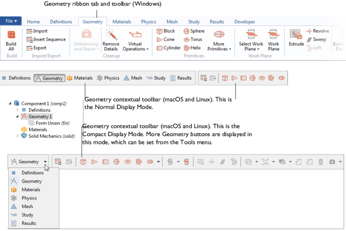
After a Component node is added to the model, the Geometry ribbon toolbar (Windows) or the Geometry contextual toolbar (macOS and Linux) is made accessible (Geometry Toolbar). Click the Geometry toolbar to display the options.
Geometric Primitives and Geometry Operations for example, can be added using these toolbars. You can also right-click The Geometry Node in the Model Builder and select any one of the available options. You can also use some drawing tools as listed in Geometry Drawing Toolbar Buttons.
Figure 7-1: Click the Geometry ribbon toolbar (Windows users, top) or Geometry contextual toolbar (macOS and Linux users, bottom) to display the options of the Geometry toolbar. This example is the 3D toolbar. Only some of the available buttons are shown in these images, and some features are not available yet, which is indicated by a grayed out button or icon. The contextual toolbar for cross platform users can also have a Normal or Compact display mode. This changes the number of geometry buttons available.
Options become available based on where in the geometry you are working. As in Figure 7-1, the Geometry toolbar has some options grayed out because these are not yet available. As a geometry sequence is built, and you select geometry objects in the Graphics window, the applicable options become available.
When one of the buttons is clicked, COMSOL Multiphysics performs the associated operation on the selected objects and creates the resulting objects, often adding a node to the geometry sequence. If you want to modify the operation, you can edit and rebuild this node. See About Highlighted Geometric Entities in the Graphics Window for details.
Drawing Geometric Primitives in the Graphics Window
In 2D and 1D, there are buttons for drawing Geometric Primitives using the mouse. In 3D, the buttons are available to create primitives, but you cannot draw these using the mouse. See Geometry Toolbar and Table 2-8 for a list of the buttons and links to the individual features.
When you move 2D geometric primitive in the Graphics window, you can use the snapping tools in the Geometry toolbar’s Draw Settings section to snap to the grid and to other geometric primitives. When snapping is enabled, a red circle appears when you click and drag a geometric primitive to indicate the current snapping point for the geometric primitive that you move. If Snap to Geometry is active, then you can snap to other existing geometric primitives’ corner points, centerpoints, and, for some types of geometric primitive such as rectangles, midpoints on the sides of the primitive.
Displaying Coordinates and Geometric Primitive Dimensions
For Windows users, the COMSOL Desktop displays the current x and y coordinates at the bottom of the desktop when you move the cursor in the Graphics window when working with the geometry. Also, when you interactively create 2D geometric primitives, the display shows the current dimensions for the following geometric primitives:
If you do not want to display this information, you can clear the Show mouse coordinates when drawing check box on the Graphics and Plot Windows page in the Preferences dialog box.
Moving and Scaling 2D Objects in the Graphics Window
For 2D geometries, you can click the Edit button () in the Graphics window’s toolbar to enter an Edit selection mode, where you can perform the following actions:
Alt-click to enter a mode where you can edit the geometry object by clicking-and-dragging control points in the Graphics window. Right-click to exit this mode; an Edit Object node then appears under the geometry objects’ nodes in the geometry sequence, and it contains the properties of the edited object. See Editing 2D Geometry Objects below.
When you work in the Edit selection mode, there is no highlighting of objects when you hover over them with the mouse. Click to select a single geometry object; ctrl-click to select multiple objects. Click outside of the geometry object to deselect.
Editing 2D Geometry Objects
Use the Edit Object () node to adjust the edges and vertices for a 2D geometry object or to add or delete edges and vertices in the object. In the Model Builder, right-click a 2D Geometry and select Edit Object.
The Edit Object function can also be started using the Edit Object button () in the Geometry toolbar:
1
In the Model Builder click the Geometry node.
2
3
Click the Edit Object button (). The Graphics window displays handles for vertices and edge control points in the selected object.
4
5
Right-click to exit the object editing mode and save the changes. A new Edit Object node is added in the Model Builder. Alternatively, if the object being edited is an Edit Object feature, the changes are incorporated in the existing feature and no new node is added in the Model Builder.
6
Another way to edit a geometry object, if you are in the Edit selection mode, is to hold down the Alt key and left-click on the object in the Graphics window. This is equivalent to selecting the object and then using the Edit Object toolbar button.
See Edit Object for details.