Physics and Variables Selection
All study step Settings windows contain a Physics and Variables Selection section, which you can use to control which physics interface (or even specific variables and physics nodes) to solve for. This can be useful for:
By default, you can select from the participating physics interfaces. To select individual physics nodes and variables, select the Modify physics tree and variables for study step check box.
Selecting Physics Interfaces to Solve For
The Physics interface column contains the names of all physics interfaces in the model. You can choose to not solve for one or more of the physics interfaces by clicking the  button in the Solve for column (by default, a study solves for all physics interfaces). Those physics interfaces are then not solved for but can still provide values for the degrees of freedom (dependent variables) according to the settings for values of variables not solved for (see Values of Dependent Variables). Click the button ( when the physics is deactivated) again to solve for the physics interface.
In the Discretization list you can specify which discretization to use. The default (and often the only) choice is Physics settings, which means that the study uses the discretization from the main physics interface node’s settings. Changing it affects the discretization order used by this study. To add another discretization, use a separate Discretization node in the physics interface. The leftmost column is usually empty but contains a warning () if the physics’ degrees of freedom are not solved for regardless of the setting in the Solve for column. This can be the case if the physics interface is not compatible with the study step.
The Multiphysics column contains the names of all multiphysics couplings in the model. You can choose to not solve for one or more of the multiphysics couplings by clicking the  button in the Solve for column (by default, a study solves for all physics interfaces). If you clear the Solve for button, any equations and dependent variables that the multiphysics coupling adds are not included, but the multiphysics coupling still affects the definition of variables.
Selecting Variables and Physics Nodes to Include
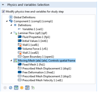
If the Modify physics tree and variables for study step check box is selected, you specify to select individual variables or physics features to include in the model that you solve. The Physics and Variables Selection section then contains a tree that is a copy of the following parts of the model tree in the Model Builder (see Figure 19-4):
Variables nodes under Global Definitions.
Variables nodes under Component>Definitions for all Component branches.
Perfectly Matched Layer, Infinite Element Domain, and Scaling System nodes under Component>Definitions for all Component branches.
Figure 19-4: An example of a Physics and Variables Selection section tree when the Modify physics tree and variables for study step check box is selected.
It is possible to include or exclude all variables, physics interfaces, and physics nodes in a study step (that are not disabled in the model tree). Select one or more nodes in the tree and right-click or use the buttons at the bottom of the section (below the tree) to change their status. Click the Go to Source button () to move to the corresponding original node in the model tree. The following options are available:
Disabling and Enabling Physics Feature and Variables Selection Nodes
Click Disable (or right-click to select from the context menu) to disable enabled nodes that are possible to disable. The contributions, conditions, or variables in a node that you disable are not included in the study when solving. You can also disable selected nodes by clicking the Disable button () underneath the tree. A disabled node is unavailable in the tree.
Click Enable (or right-click to select from the context menu) to enable disabled nodes. The contributions, conditions, or variables in a node that you enable are included in the study when solving. You can also enable selected nodes by clicking the Enable button () underneath the tree.
When you right-click, the following context menu options mean that a node cannot be enabled or disabled:
Cannot be Disabled — for default nodes in the physics interfaces.
Disabled in Model Builder — for nodes that you have disabled in the Model Builder.
Not Applicable — for physics nodes that are not applicable for the study type in the study step. The item in the tree is not available.
When solving, equations and variables are generated as if the disabled nodes in the tree were disabled in the Model Builder. This means that the nodes’ selections override each other as if the nodes were disabled in the Model Builder.
Change of States and Override and Contribution Indicators
An asterisk displays in the upper-right corner of nodes for which the state has been changed in the study step’s selection tree compared to the state in the Model Builder. In this example, under the Physics and Variables Selection section, a Transport in Diluted Species interface () is disabled (unavailable), provides no degrees of freedom (red dot in the lower-right corner), and has a change of state indicated by the asterisk. The asterisk means the Laminar Flow interface in the Model Builder is not disabled. Also see Figure 19-4 for another example. In general, any variable or physics node in the Model Builder that is disabled in any study step gets an asterisk in the upper-right corner. For physics interfaces, this applies also when you have not selected the Modify physics tree and variables for study step check box and the physics interface is disabled in the Solve for column in the Physics and Variables Selection section.
The dynamic visual icon indicators for overridden and contributing nodes also appear in the tree in the Settings window for the study steps when you have selected the Modify physics tree and variables for study step check box in a study step’s Settings window. When you select a physics node in the tree, the override and contribution icon indicators appear in the same way as in the Model Builder when you select a physics node, but if you disable any physics node in the study step’s tree, the icon indicators then show how the physics node overrides and contributes to the model when one of more physics nodes are disabled in the study step.
Options and States for the Physics Nodes
The following options are available for the main physics nodes under the Physics and Variables Selection tree. Right-click a node and select one of the following from the context menu or click the button beneath the tree (see Figure 19-4). Selecting these options affects the entire physics interface. Select:
Solve For (the default setting) to solve for the physics interface, including all enabled physics nodes and the contributions, constraints, and variables that are added. This is similar to the button when you specify what physics interfaces to solve for without the selection tree.
A physics interface in this state shows a small green circle in its lower-right corner to indicate that the study step solves for the degrees of freedom (dependent variables) in the physics interface and features. This is an example of a Laminar Flow interface with the green dot ().
Disable in Solvers to not solve for the physics interface but provide degrees of freedom (dependent variables) and other physics node variables using the settings for values of variables not solved for (see Values of Dependent Variables).
A physics node in this state shows a small yellow square in its lower-right corner to indicate that the study step provides degrees of freedom but does not solve for the physics interface or feature nodes. In this example, a Laminar Flow interface is both showing that it provides degrees of freedom (yellow dot in the lower-right corner) and has a change of state indicated by the asterisk ().
Disable in Model to fully disable a physics interface or node in the model. The physics interface or node does not contribute to the study and no variables, including the degrees of freedom (dependent variables), are included.
A disabled physics interface or node is unavailable and shows a small red square in its lower-right corner to indicate that the study step provides no degrees of freedom for it. In this example, a Transport of Diluted Species interface () is disabled (unavailable), provides no degrees of freedom (red dot in the lower right corner), and has a change of state indicated by the asterisk.
In addition, the physics node can be in the following states:
If the physics interface or node is not applicable because it does not support the study step, then by default it has the Disable in Solvers setting, and you can also choose Disable in Model. Solve For is not available.
Frame Control for Mesh Deformation
Multiple physics interfaces controlling the same frame are not allowed on the same selection. It is, however,. possible to use multiple frame-controlling physics with overlapping selection, but you then have to explicitly disable frame control on all but one of the physics. You can choose different physics to control the frame in different study steps. In the physics tree, frame-controlling interfaces have the label Controls spatial frame or Controls material frame. Toggle the frame control on those physics interfaces by selecting them in the tree and toggling the Control Frame Deformation button () in the toolbar or by right-clicking the physics interface node and selecting Control Frame Deformation from the context menu.
Discretization Selection
You can also right-click a physics node in the selection tree to select the discretization. The discretizations appear at the bottom of the context menu (underneath the horizontal divider). In most cases, the only option, and the default, is Physics Settings, which takes the discretization from the physics interface’s Settings window, but if you have added separate Discretization nodes, you can select from one of those instead of Physics Settings.
If you have the AC/DC Module, see Electric Shielding: Application Library path ACDC_Module/Resistive_Devices/electric_shielding.