The Component Node
A model component is a fundamental part of the model and contains a geometry with its associated physics interface, mesh, and variables and other definitions that are local to that component. The Component node defines the namespace for each part of a model that is defined in a model component. A model can have several Component nodes. For example, if you are setting up a system model using both a 2D simplification — represented in one 2D Component branch — and a full 3D description in another Component, these can both be added to the Model Builder to represent different aspects or parts of the model. You can couple variables between different components in a model using coupling operators.
To Add Physics and Add Mesh to the Component, from the Home toolbar, or for any operating system, right-click the Component node. See The Add Physics Window, and Creating a Mesh for Analysis for more information.
The Component node icon also indicates the space dimension:.
Adding a Component to a Model
You can create models with multiple geometries by adding one or more Component nodes to the Model Builder.
To add a Component node or nodes:
Right-click the Root node (the top most node) in the Model Builder and select Add Component (see The Root Settings and Properties Windows).
In The Model Wizard on the Select Space Dimension page, select 3D, 2D axisymmetric, 2D, 1D axisymmetric, or 1D. Continue defining the model as in Creating a New Model.
The Default Nodes
Figure 3-1: An example of the Model Builder default nodes for the Electric Currents and Heat Transfer in Solids interfaces.
These default nodes are normally added under a Component node:
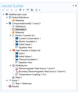
Definitions: Contains user-defined variables, selections, views, pairs, functions, probes, component couplings, and coordinate systems, which are defined locally for the model. See Global Definitions, Geometry, Mesh, and Materials for information about using these local Definitions () and Global Definitions (). Use Global Definitions to define Parameters, Variables, Functions, and loads and constraint groups with a global scope — that is, groups that are not specific to one Component node.
Geometry (): Contains the sequence of geometric objects and operations (or imported CAD data) that defines the model geometry.
Materials (): Contains the materials and material properties used as sources for material data in the component. See Materials for detailed information.
Physics interface (): Any added physics interface displays as a node under Component (Solid Mechanics in Figure 3-1 for example).
Multiphysics (): When a multiphysics interface is added to the Model Builder, this node contains all the relevant multiphysics features for that interface. See Multiphysics Modeling Approaches for more information.
Meshes (): Contains the sequences of mesh operations that defines the computational meshes for the model. When there is only one mesh in the model, its Mesh node appears directly under the Component node.
The Settings window has the following sections (also see Figure 3-3):
The label appears on the node as the default node name. The default label is Component 1, but you can change it in the Label field.
The name is a string used to define a namespace for the model component and identify variables defined in that component. The default component name is comp1, comp2, and so on, but you can change it in the Name field. See Settings and Properties Windows for Feature Nodes and Displaying Node Names, Tags, and Types in the Model Builder for more information.
General
This section contains general settings that you normally do not need to change:
Unit System
The default setting in the Unit system list, Same as global system, is to use the global unit system, which you specify in the root node’s Settings window. If you want to use another unit system in a model, select it from this list.
Spatial Coordinates
The default names for the spatial coordinates are x, y, and z for 3D as well as planar 1D and 2D geometries. For axisymmetric geometries, the default names for the spatial coordinates are r, (phi), and z. If you use the geometry to represent something other than space, or if you for some other reason want to use other names for the spatial coordinates, you can change the names in the fields for the First, Second, and Third coordinate under Spatial coordinates. The field labels include the default spatial coordinate names in parentheses.
You cannot use the variable for the time, t, as a spatial coordinate name.
Geometry Shape Order
The setting in the Geometry shape order list determines the order of the curved mesh elements that determine the geometry shape. The default setting is Automatic, but it is also possible to select an order such as Linear, Quadratic, Cubic, Quartic, Quintic, Sextic, and Septic. The default setting allows for automatic reduction of the order in some cases.
Curved Mesh Elements in the COMSOL Multiphysics Programming Reference Manual