The Component node has different icons based on space dimension
0D (

) (no space dimension),
1D (

),
1D axisymmetric (

),
2D (

),
2D axisymmetric (

), and
3D (

).
On the Select Physics window, there are different ways to select one or several physics interfaces to add to the model. There are also interfaces for PDEs, ODEs, and DAEs under the
Mathematics branch.
Under Added physics interfaces (see
Figure 2-12), click any interface to open the
Review Physics Interface page. Here you can review and optionally modify any
Dependent Variables names and, for some physics interfaces, specify the number of dependent variables. For other physics interfaces you can edit both the name of the field and the field components. Examples of fields with components are the displacement field in a Solid Mechanics interface and the Velocity field for a Laminar Flow interface.
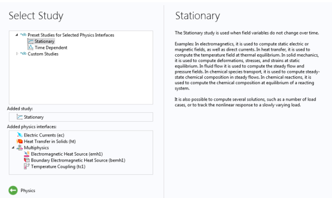
On the Select Study page, click to select the type of study to perform. The available options depend on the set of physics interfaces included in the model. Some study types are applicable to all physics interfaces for which you choose to solve, while others are not, but all are in some way available. You can select the study type from one of the following branches (see
Figure 2-13):
After clicking Done, the
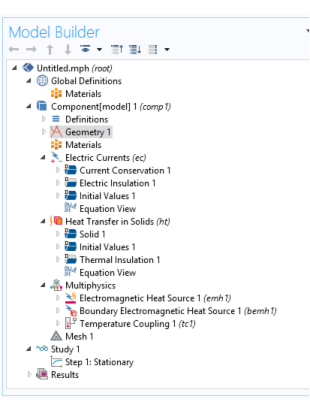
Model Builder window displays a model tree with a set of default nodes in the
Component branches:
Definitions,
Geometry,
Materials,
Mesh, and nodes based on the physics interfaces selected (see
Figure 2-14). The
Component nodes and branches form the sequence of operations that define the model.


