Simplified Modeling of Fasteners
Applicability
The Fasteners node is designed for the approximate modeling of large numbers of fasteners. Its primary use is for rivets, but with certain assumptions it can also be applied to bolts and similar connectors. For spot welds, a dedicated node is available and is described in Modeling Spot Welds.
Because the Shell interface does not represents stresses in the direction normal to the shell, any prestress in the fasteners is ignored. In contrast, the Solid Mechanics interface allows the inclusion of a preload in the fastener analysis.
When modeling pretensioned fasteners, it is important to include the contact between the connected plates, as most of the load is transmitted through the joint via contact pressure or friction force. The total load is the sum of the load carried by the bolt and the load carried through the joint. As the applied load increases, the bolt load increases while the contact forces decrease, until the plates separate. At this point, the entire load is carried by the bolt, which is then considered as a loose bolt.
In the absence of preload, the forces are transmitted solely through tension and shear in the fastener. This is a common assumption when modeling rivets. When using the Shell interface to model pretensioned bolts, this approach leads to the following consequences:
These limitations are, to a large extent, related to the local stress evaluation in the bolt. However, there is also a certain underestimation of the stiffness. This can, to some extent, be mediated by increasing the fastener stiffness.
Modeling Using the Fasteners Node
A fundamental assumption is that the fastener hole is present in the geometry of both plates to be joined. The actual connection occurs between two sets of hole edges, or boundaries. As long as the pairs of holes are coincident within some tolerance, all fastener locations can be found automatically. This is the standard way in which you set up a model using the Fasteners node.
A Fasteners node has one or more Hole Selection subnodes. The automatic selection mode is invoked by the choosing Automatic in the Fastener Hole Detection section in such a subnode.
For two holes to be automatically connected by a fastener, the following criteria must be met:
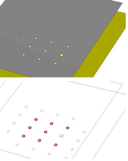
When the selection entity is set to boundary, select Search annular shape only to detect holes that have surrounding boundaries with annular shapes. The center of the inner and outer circles may differ within a certain tolerance (Annular center offset).
In Figure 2-37, an automatic fastener connection is illustrated. In the upper (gray) plate there are 16 holes. Nine of them have a matching hole in the lower (yellow) plate. One of these holes, however, have a larger diameter. With the default tolerances, eight fasteners will be generated. In the lower part of Figure 2-37, the result template Connected Region Indicator is shown. This plot is an important tool for checking several types of connections.
Figure 2-37: Example of automatic detection of fasteners.
If the conditions for hole matching above are not fulfilled (or cannot be fulfilled by reasonable changes of the tolerance values), you will need to make manual selections for the holes. In that case, you need one Hole Selection subnode for each fastener. Change the setting to Manual in the Fastener Hole Detection section, and make the appropriate entity selections. By using Group by Continuous Tangent, it is easy to select all edges around a hole. In this mode, it is not possible to create more than one fastener per Hole Selection subnode.
You can mix automatic and manual selections under the same Fasteners node.
When analyzing riveted structures, it may be necessary to also model contact between connected parallel plates in order to avoid that they penetrate each other. In most cases, a set of fasteners will constrain the plates to such an extent that the advantage of actually including contact in the model is small.
When analyzing pretensioned fasteners using the Solid Mechanics interface, it is necessary to model contact between the connected plates.
In the Shell interface, the sides of the shells (top or bottom) that are to be connected must be known. The information is used for two purposes: to connect the correct set of displacements, and to compute the distance, including the shell thickness and offset. With the default settings, Automatic, the two sides of the shells that are found to be closest to each other are connected. However, such an automatic search can take a significant time if many boundaries are coupled, or there are many mesh elements. If this is a problem, you can:
In the Advanced section in the settings for Fasteners, change the Search method to Manual, and set a suitable Search distance.
Results
In many cases, you are only interested in the fasteners as a means of obtaining a proper global stiffness of a structure. You can, however access the results in the individual fasteners. There are two result quantities: the axial force and the shear force.
From the Result Templates window, you can add
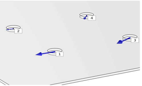
A Fasteners Forces plot group, to visualize the normal and shear forces at each fastener, and a label showing each fastener number. Normal forces are plotted as green arrows, and shear forces as blue arrows. The coloring can be affected by the addition of a Safety subnode. To display the fasteners forces, these have to be evaluated first using the Fasteners Normal Forces and Fasteners Shear Forces evaluation group.
A Fasteners Normal Forces evaluation group that contains a table of the location, the normal forces, and the damage index of all fasteners. This table has to be evaluated to display the forces in the Fasteners Forces plot group.
A Fasteners Shear Forces evaluation group that contains a table of the location, the shear forces, and the damage index of all fasteners. This table has to be evaluated to display the forces in the Fasteners Forces plot group.
A Fasteners Forces Magnitude evaluation group that contains a table of the normal and shear forces magnitude of all fasteners. In the table, click Show Row Numbers to display the number of each fastener.
Figure 2-38: Example of a results from a Fastener Forces plot group.
By adding a Safety subnode under Fasteners, you can evaluate the degree of utilization for each fastener.
The damage criterion is
Here, Fn,max and Fs,max are the critical forces in tension and shear, respectively. The exponents αn and αs are often chosen as 2 for rivets, while other choices are common for bolts, for example α= 2 and α= 3.
If the allowable forces are exceeded, that is
then the forces in the Fasteners Forces plot group will be colored in red.
You can manually specify a Safety factor sf0 to evaluate the intermediate degree of utilization before failure, that is
In this case, the forces in the Fasteners Forces plot group will be colored in orange.
You can also specify a Margin of safety ms0, which is related to the safety factor as